Tuesday, June 24, 2025

Paint Disaster, more bodywork

So, one of the conclusions I arrived at after my previous attempt at mounting the fuel filler neck in the front of the freeway was that I needed to rework how the fiberglass is laid out so the filler mount is horizontal. Basically, I need to inset a pocket into the fiberglass nose which it can sit down into.

So, I’ve got a fairly well understood process for matching the weird surface curves at this point.

  • Spray with 3d scanning spray.
  • Put a object of known size in the frame
  • Wave my phone slowly around and take a video
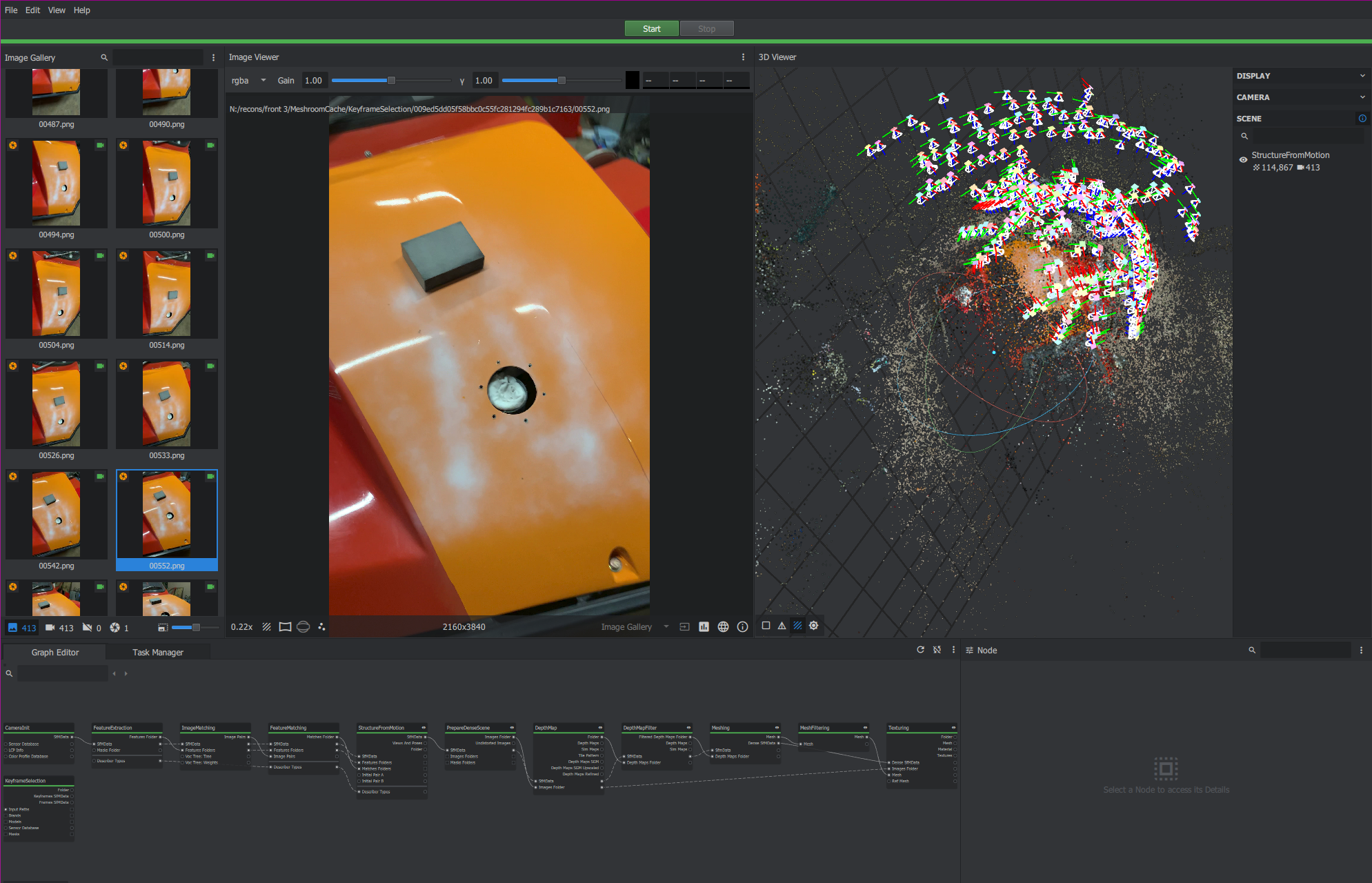
  • Shove into meshroom. Extract frames from the video, and run the default mesh pipeline
  • Bring geometry into Fusion 360. Fit a surface to the (rough) mesh.
  • Design a negative of the new body shape. Also design a template that will key off existing geometry to figure out where to cut
  • 3D print the mold
  • Paint + wax the mold
  • Fiberglass!
mesh_3.png

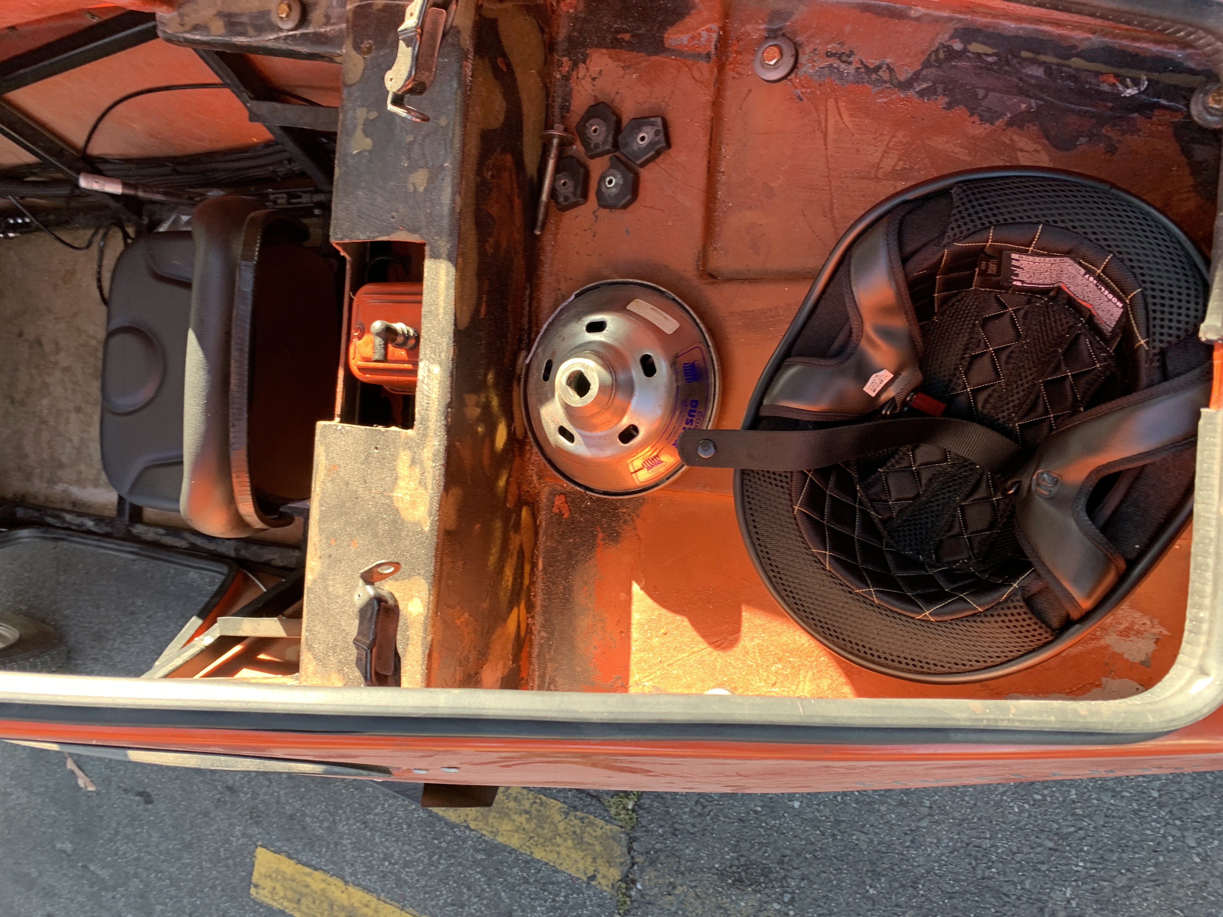
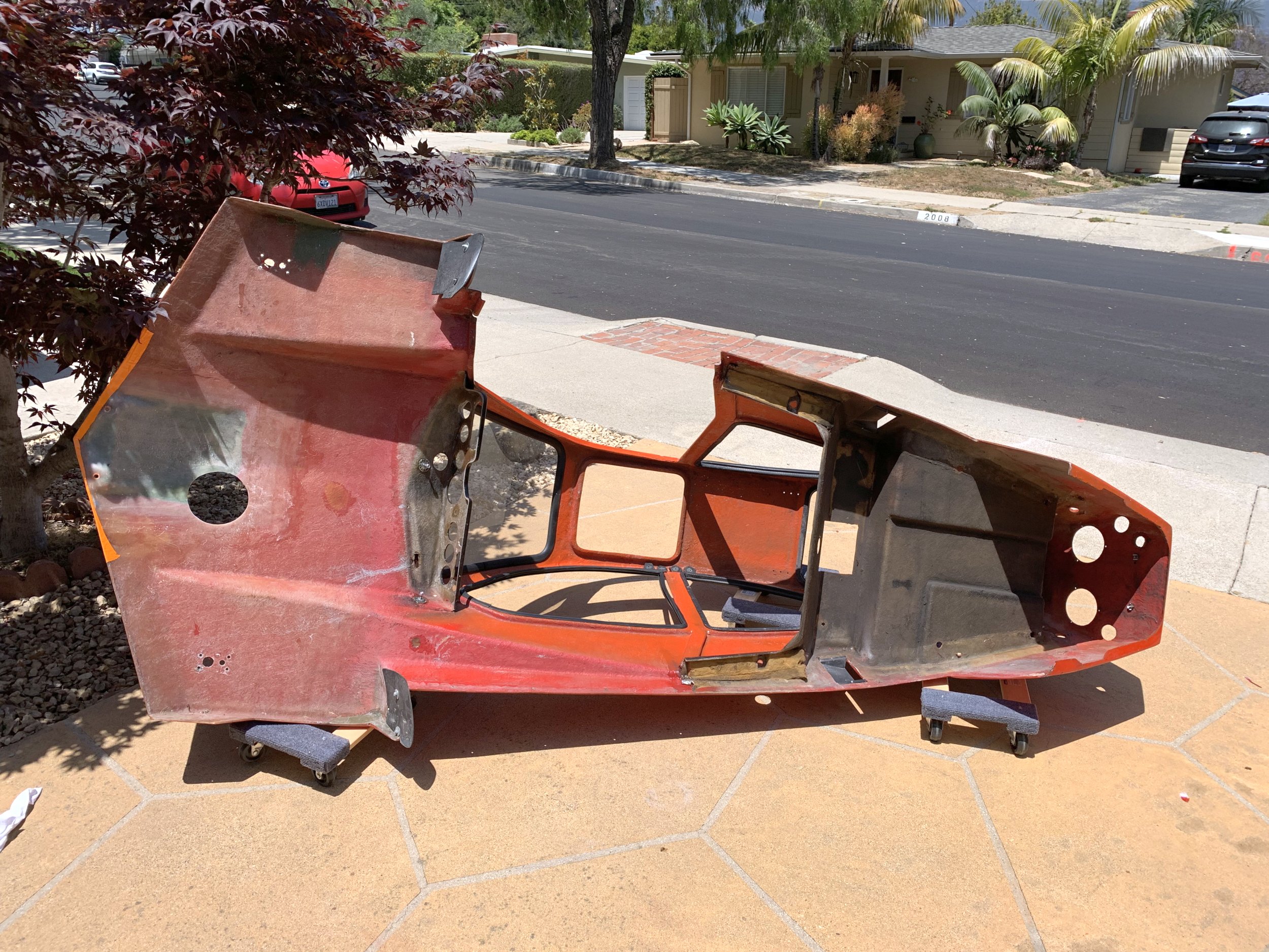
I took the body off, and expanded the fuel filler hole to fit the new geometry.

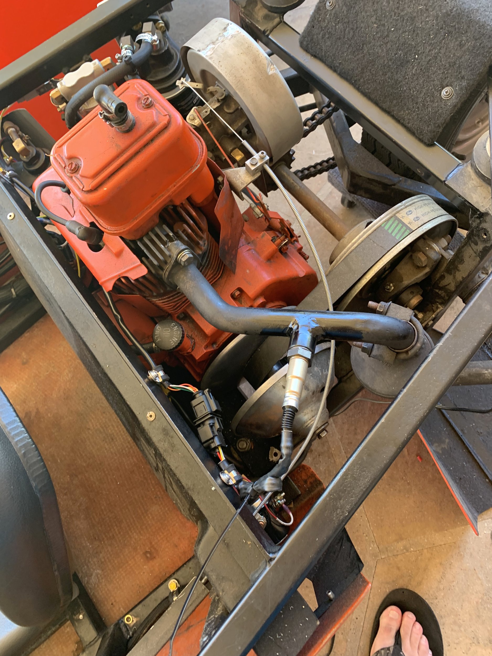
Since I had the body off, I also took the opportunity to finally powerwash the underside of the top-half. In particular, the rear area over the engine had a light film of oil and road-grime that had been annoying me.

IMG_8299.jpg

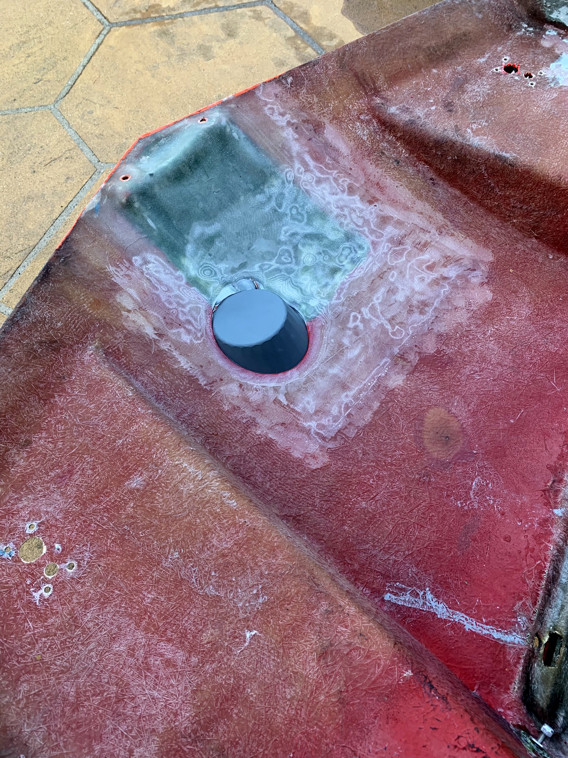
I then sanded out the existing fiberglass to give a proper surface finish for the newly added glass to properly adhere. I also feathered the fiberglass around the mold (grey lump) in the below image to make things join more cleanly.

IMG_8300.jpg

I also went around with a smaller sanding pad and cleaned up a bunch of areas on the underside where there was crappy fiberglass work from the manufacturer:

IMG_8303.jpg

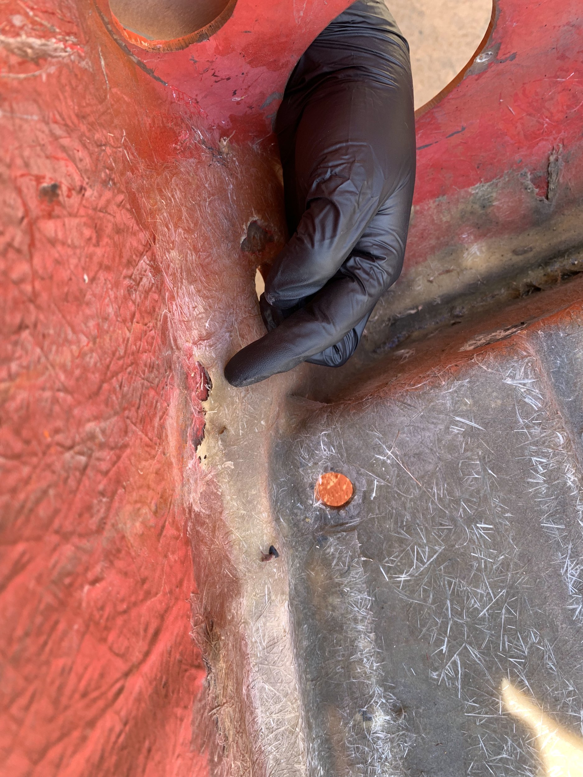
When HMV was bonding the engine cover section into the overall body, they really half-assed the fiberglass mat in the tail section. While this is really not a actual issue with the body from a structural perspective, the poor workmanship bothered me, so I sanded these back as well and patched them in with small bits of fiberglass cloth.

IMG_8305.jpg

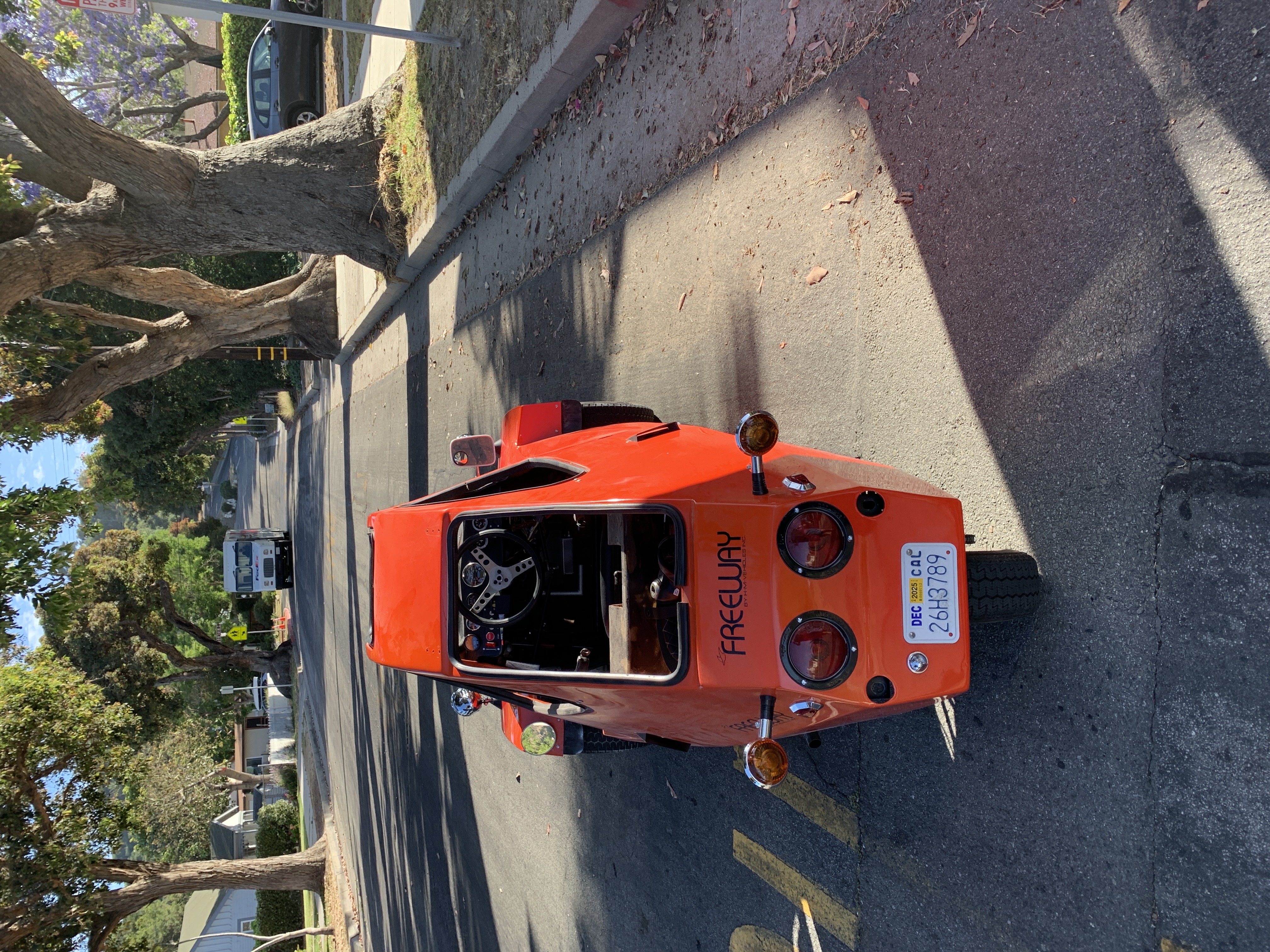
One thing I think is pretty clear at this point is that while I appreciate the Freeway for what it is, I’m not at all precious about it being “original” or anything. One part I particularly dislike is the rear engine/wheel cowling area. It both looks pretty terrible (in my opinion) and the fiberglass in that area is also very thin and starting to fail.

The shape of it also makes installing/removing the body top a lot more annoying.

I took this opportunity to cut a bunch of it away entirely.

IMG_8306.jpg

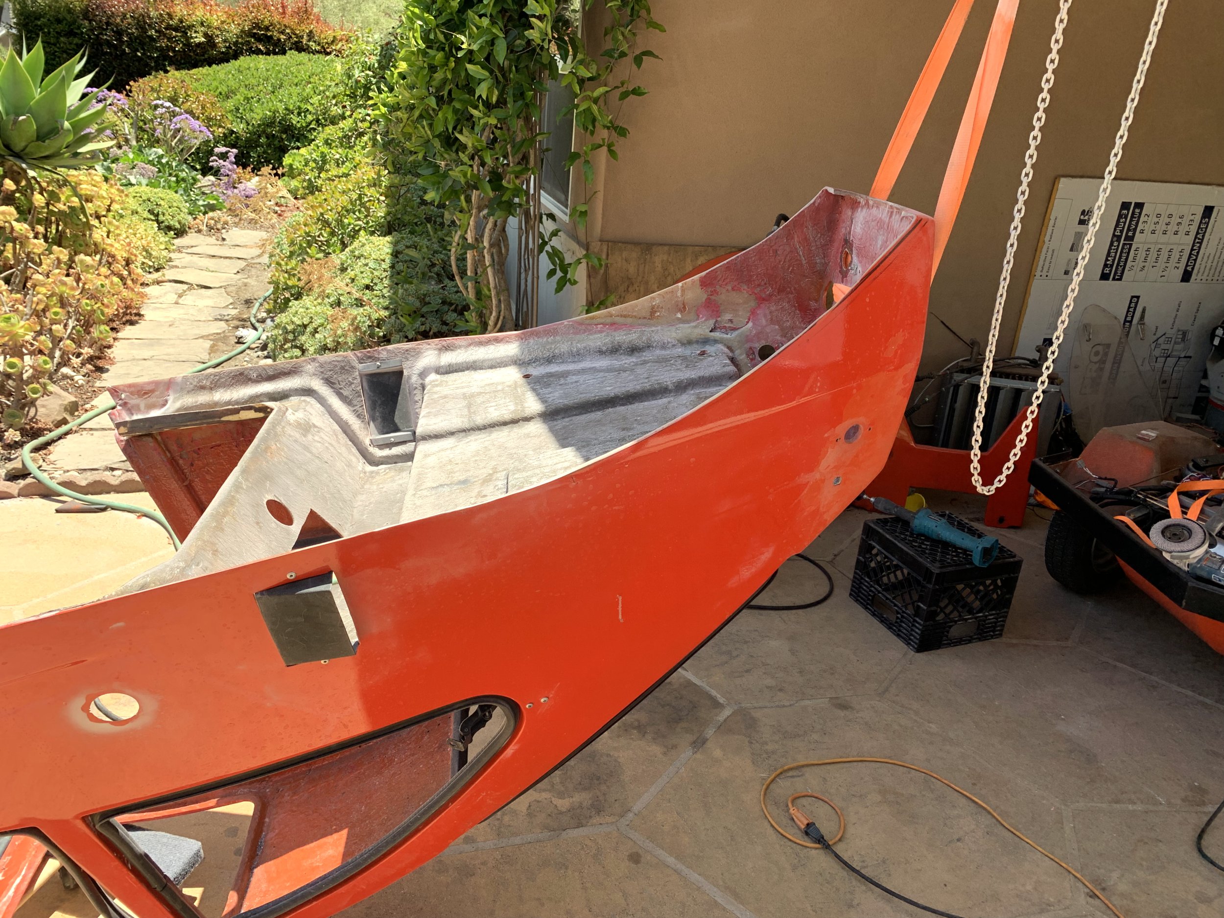
I think this improves the body-lines a lot, and also will make access to the rear wheel and engine area a lot more convenient. I also feathered the fiberglass edges around the original fuel filler neck hole, so I can patch that in the future.

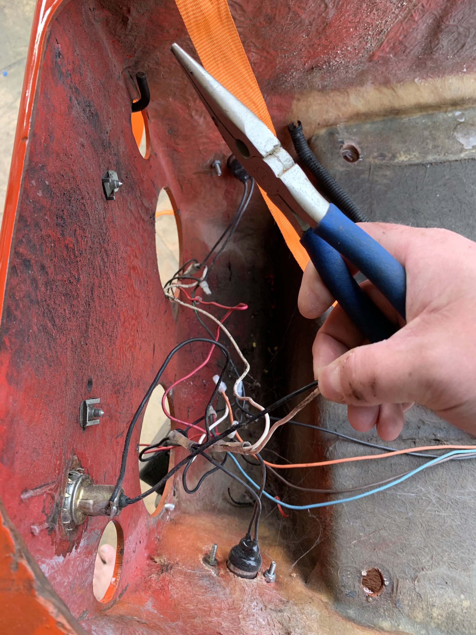
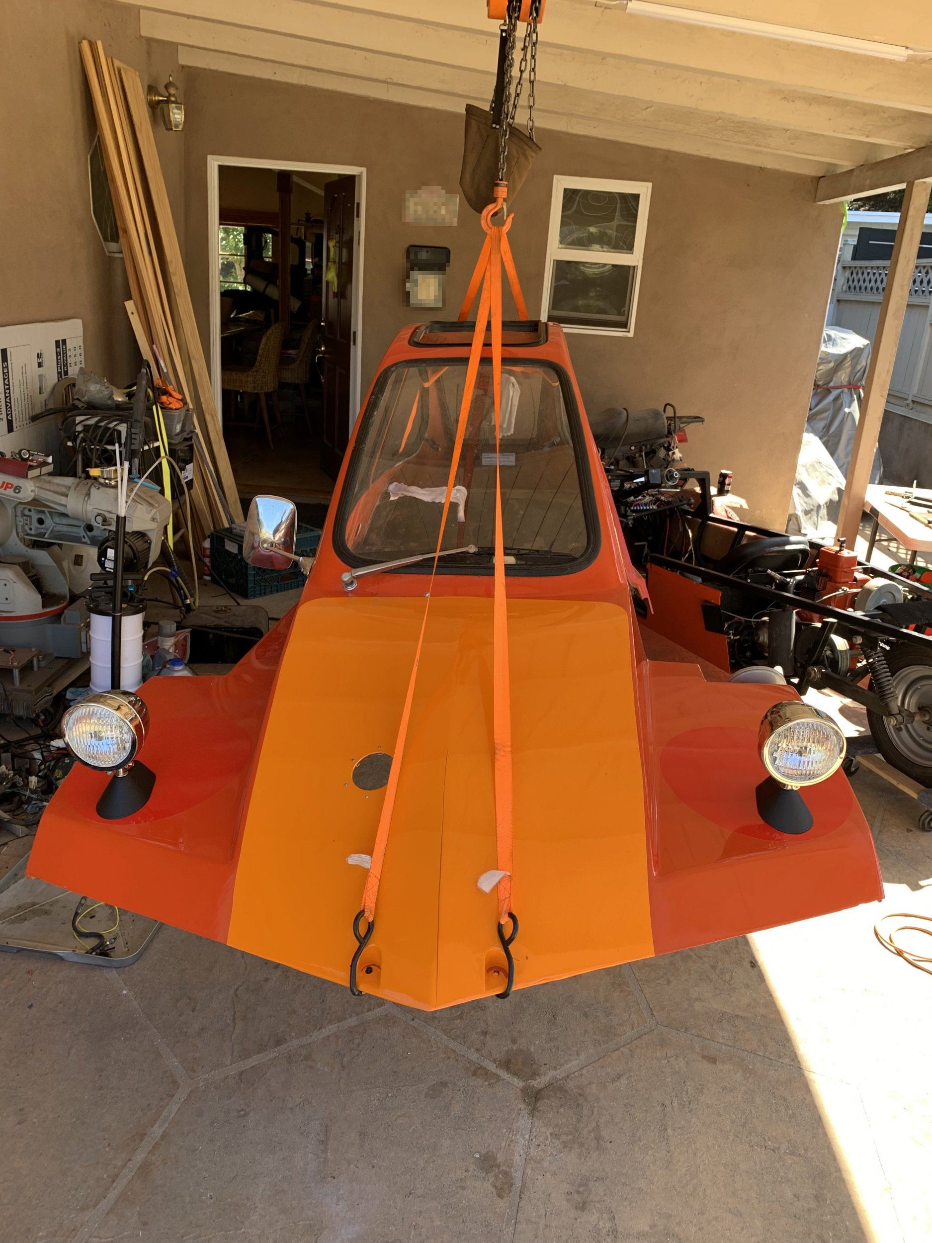
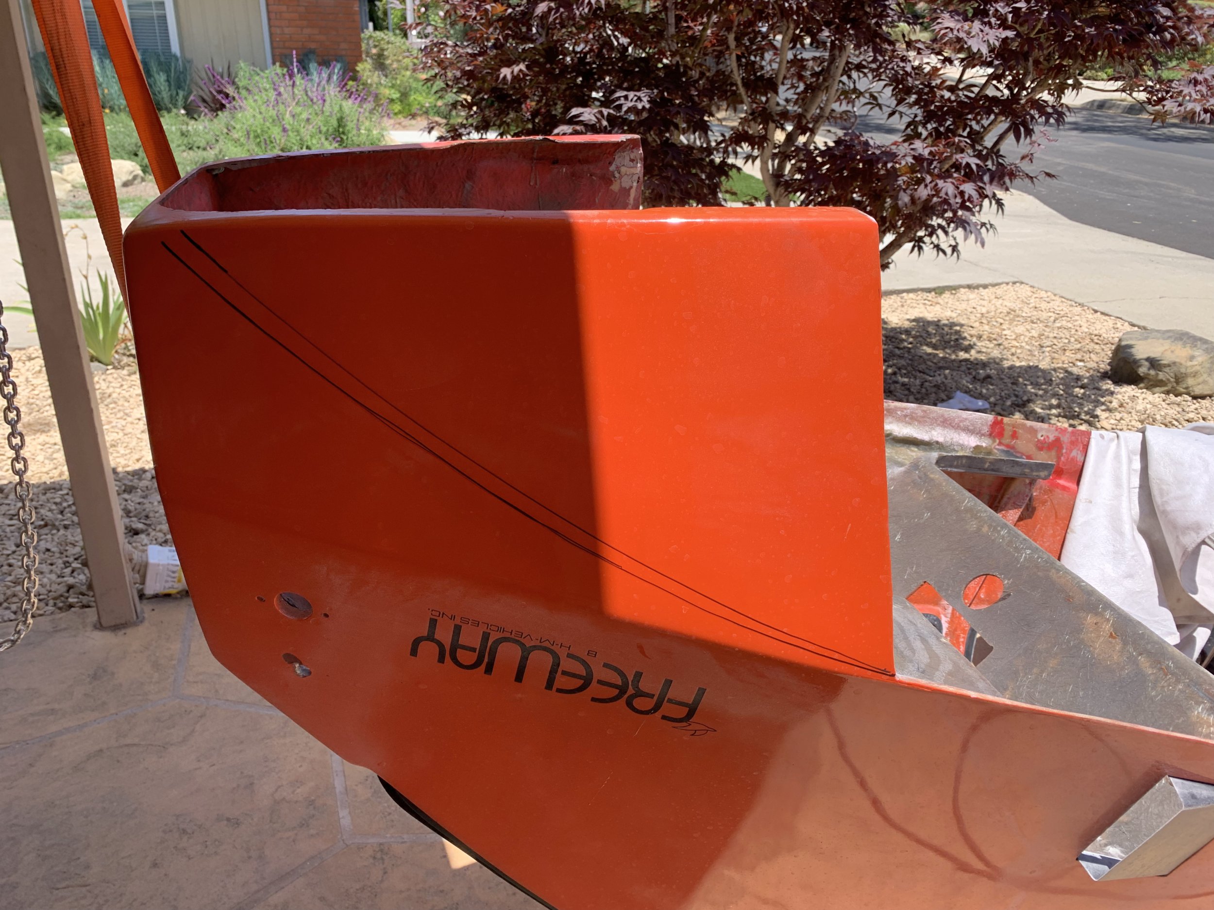
So, the final issue I had here is that after I had done all the fiberglass work, I was powerwashing the body again, primary to remove some of the vinyl stickers I had been experimenting with, and well, apparently whoever did the orange/red paint on top of the original red paint did a completely shit job.

IMG_8308.jpg

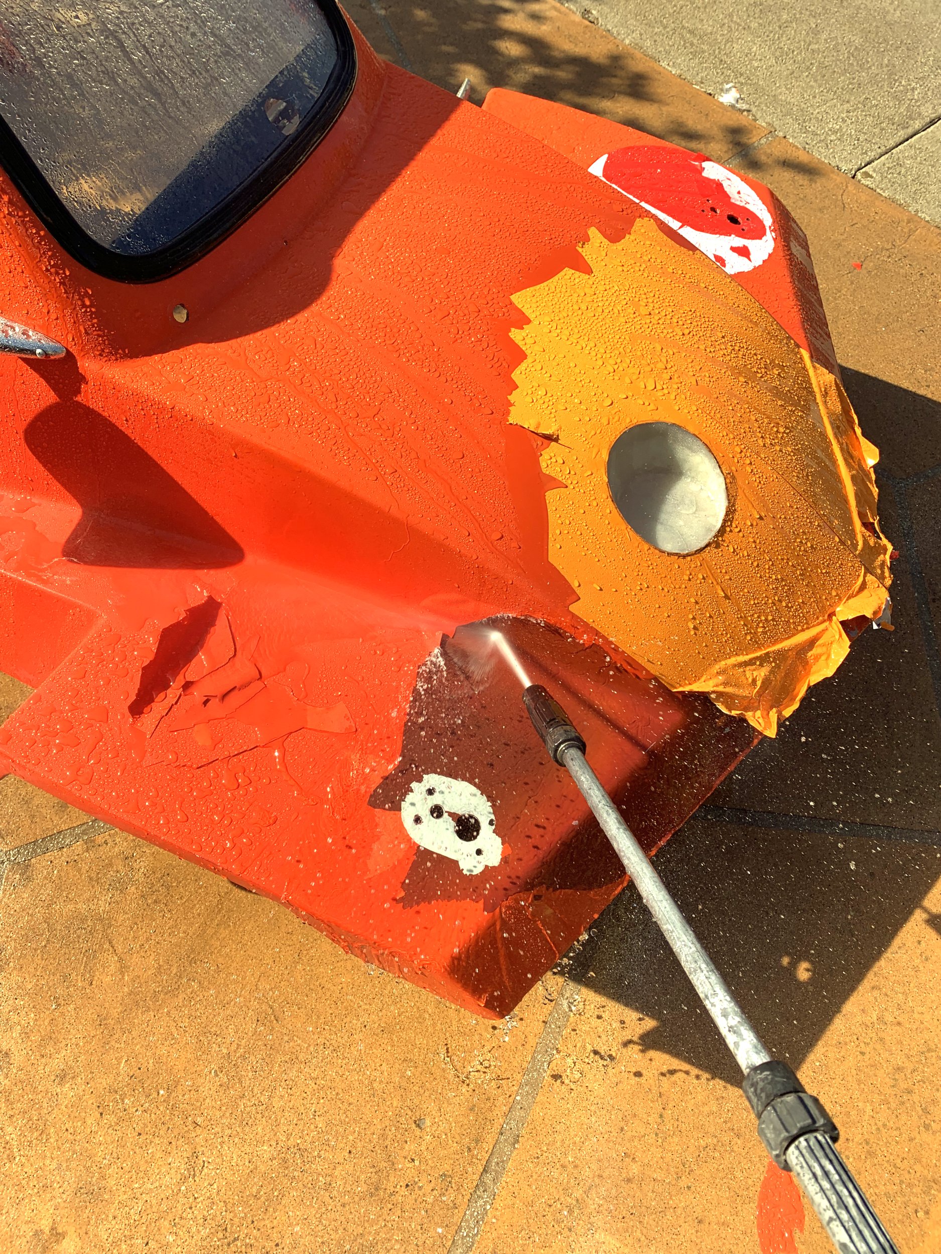
The powerwasher caught under an edge and wound up lifting a huge section of the paint layer in seconds. There is about zero adhesion between the primer layer on top of the original paint and the color coat (the clearcoat is also barely adhering, but that’s not the issue here).

IMG_8307.jpg

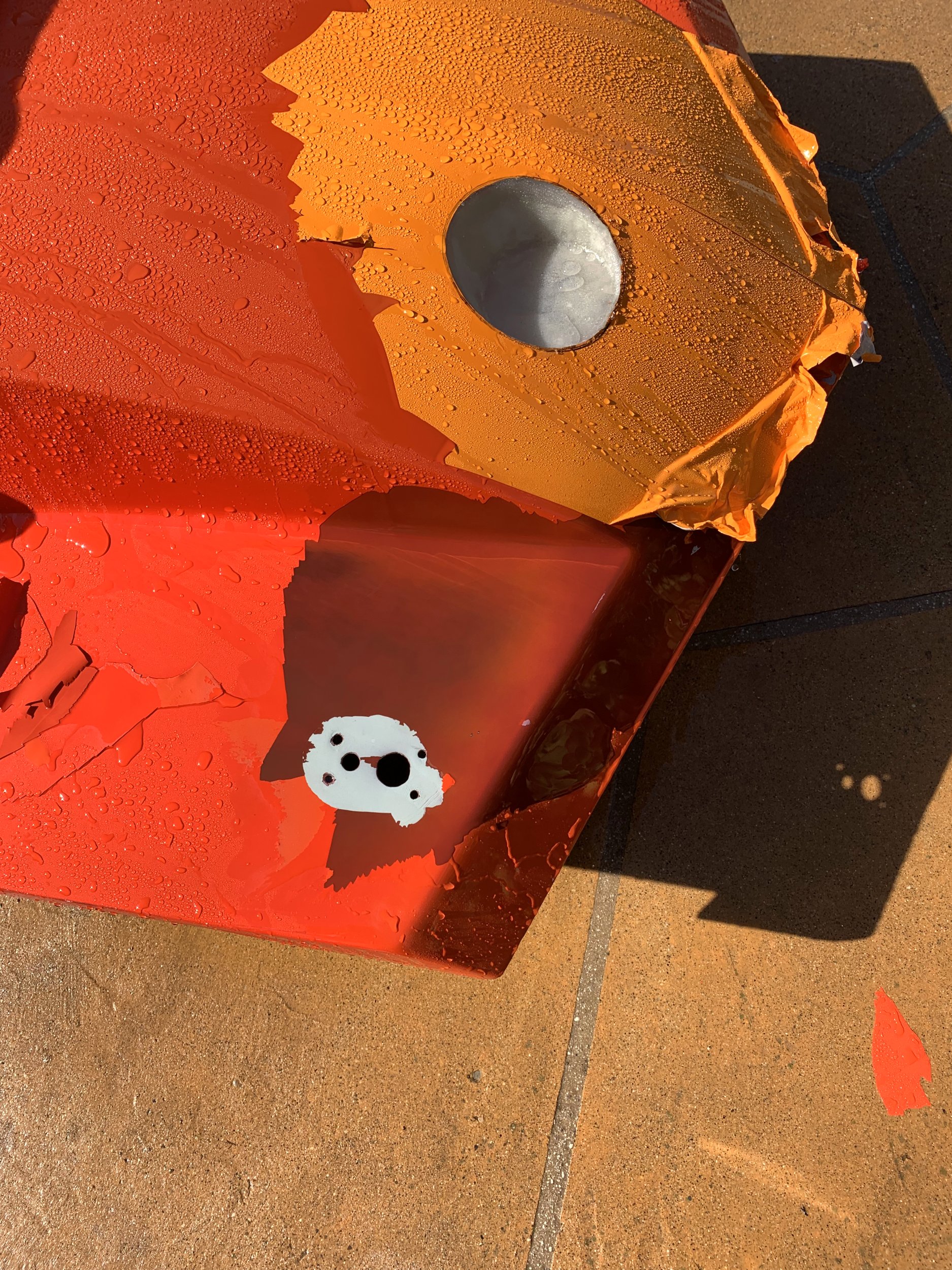
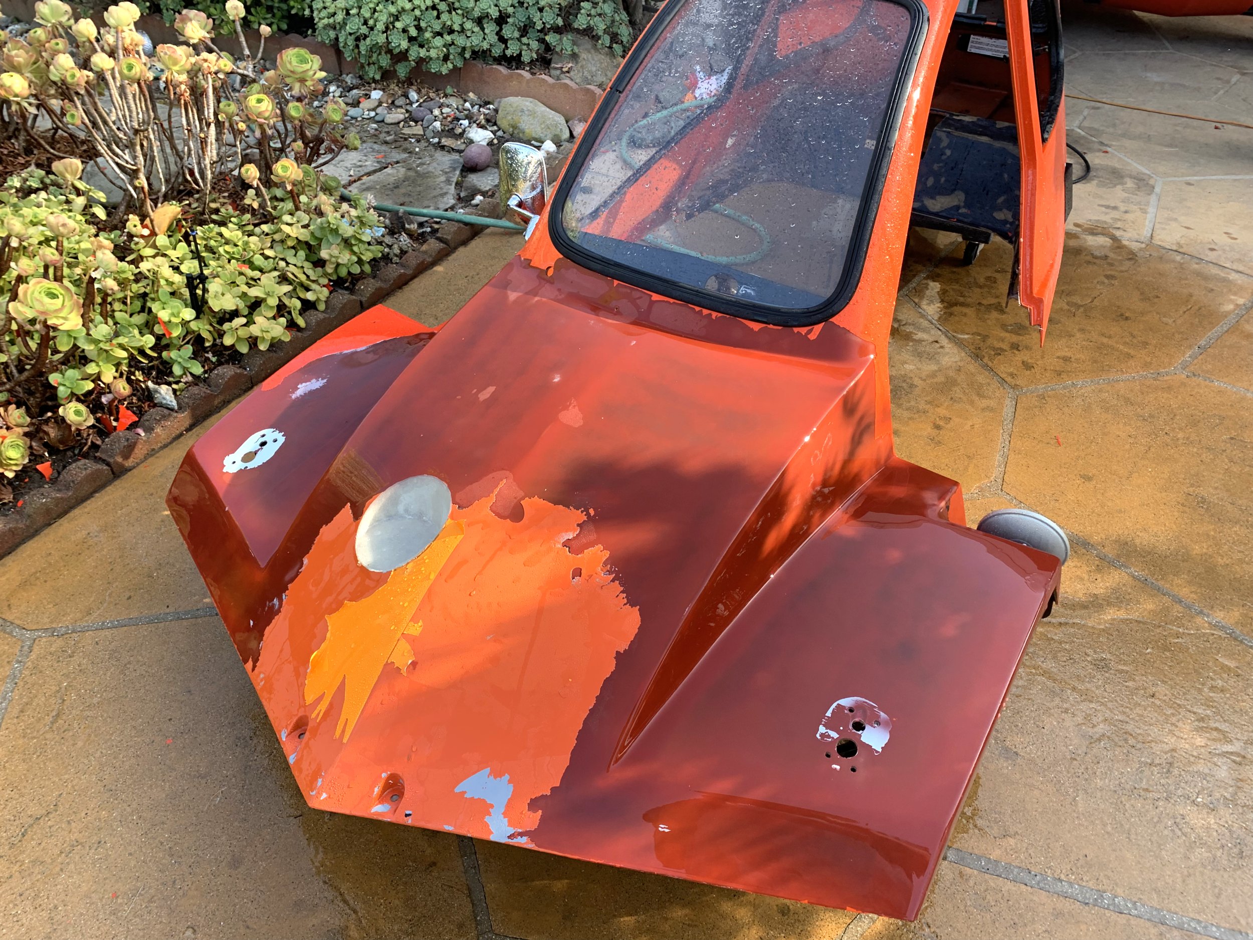
Anyways, after a hour or so with the powerwasher, the entire front end is basically stripped of paint.

IMG_8309.jpg

You can also see the newly shaped fuel filler hole here. The mold came out quite well, though I had to pry a bit to get it to finally pop out.

Considering this was effectively the first time I’ve ever attempted fiberglass molding, I’m pretty damn happy with the result. I think I should have used a couple more coats of partall wax (or I wasn’t layering it on thick enough), but it came out without issue in the end, despite pulling a bit of the paint from the mold surface. I’m also super encouraged by the idea of making a mold for a rear internal fender.

At this point, I’ve more or less concluded I’m going to have to either repaint the entire upper body section, or have another go at vinyl wrapping it. The vinyl wrap sticks SUPER well to a surface with a bit of a key to it, and I think most of my trouble with my previous attempt was that I thought I needed to do the entire area with one single vinyl section. I believe if I do the coating in multiple sections, it should be a lot more tractable. It’ll have seams, sure, but hopefully I can live with that.

I don’t have a lot of pictures of the work here (or most of the fiberglass stuff), since it’s a very messy process and I’m wearing gloves with either resin or lots of fiberglass dust on them for most of it.

Monday, June 16, 2025

First Run-Testing of the reassembled Freeway

So, I had the freeway mostly assembled (I haven’t re-installed the door), and I couldn’t resist taking it for a test drive even with a bunch of wiring dangling everywhere.

In retrospect, this wasn’t the brightest idea.

It runs fine, though I did discover a number of minor issues.

I don’t think the front brakes are completely bled. Or the brake balance is just terrible in general. The front brakes work, but by the time they engage firmly, the rear brake is on the edge of locking the rear tire up. Considering I did a one-person bleeding job for the front brakes, I strongly suspect I just need to re-bleed them with someone to help.

The tachometer doesn’t work. I was guessing that I could pick a RPM signal off the same wire used for engine-kill. Either this isn’t true, or I derped the wiring somewhere. This isn’t a huge deal, I just need to poke it with an oscilloscope.

I have the switch for the O2 sensor power and the oil pump power reversed (just need to swap the terminals).

The major issue is that apparently I didn’t tighten the drive clutch pulley fastening bolt enough. I was ~0.5 miles from my house when I heard a loud BANG, and the movable sheave of the belt-CVT assembly went flying off to my left in two sections.

IMG_8289.JPG

It was not fun having to push the thing home.

IMG_8290.JPG

Freeway Gauges!

So, one area where I let things get a bit out of hand was the gauge situation on the freeway.

These originally came with 4 gauges: Speed, oil temp, fuel level, and battery current (plus and minus).

The Speedo is GPS-based. The original speedometer got water-damaged somehow, so the previous owner (tried) to replace it with a GPS unit. Somehow, when I took possession of the vehicle, it only worked when the engine was not running. I’m not sure how that was managed, I didn’t bother tracing any of the wiring since I have an original wiring diagram, and was planning on replacing all the wiring anywas.

Since I’m a nerd, I added a tachometer, a voltmeter and one more.

signal-2025-06-14-180052.jpeg

So one of my housemates is a jerk, and made a sarcastic comment about a O2 sensor. Well….

signal-2025-06-14-195722.jpeg

(Trust me, these welds looked really terrible before I ground them nice.)

IMG_8287.jpg

Terriblwelder strikes again, and I now have a O2 bung in the exhaust, and a Chinese clone of an AEM 30-0300 Wideband AFR gauge installed in it.

I had to shop around a fair bit for a bung that would work here, since most O2 sensor bungs have the sensor protrude maybe 1/4” into the exhaust pipe. Since the exhaust pipe here is about 1” ID, that would substantially occlude the pipe.

I managed to find a bung where the O2 sensor tip just barely peeks into the pipe ID when it’s fully screwed in. This isn’t a high performance application, I can handle the sensor response being maybe a tiny bit sluggish.

I can also confirm that the carb tuning is terrible. It idles around 10:1 AFR currently, which makes sense (it smells rich just running). I’ve not had it under load running yet.

——–

I also took the opportunity to helicoil one of the exhaust flange bolt holes, as it was on the edge of the threads being completely gone (the bolt in it did screw in, but it could rotate continuously with just a bit of resistance).

IMG_8285.jpg

Wiring the Freeway.

Like most of my projects, the wiring for the HMV Freeway got a bit out of hand.

IMG_8227.jpg

Electrics are an area where I’m quite comfortable, as some of what I do at work is effectively electrical engineering. In this case, I’m playing around using only relays, but well, I kept adding things I wanted, or needed a DPST relay to invert something, or so on.

Everything is pretty carefully fused. I also relocated the battery up to the front area. The black box in the above image contains a lithium motorsport battery.

I have no idea how they do it, but the thing is ridiculously tiny, and weighs basically nothing. I’m guessing they’re basically those jump-starter packs in a battery case, with a integrated battery manager that somehow handles the charging and handles the lead-acid float-charge behaviour.

In any event, it seems to have plenty of gumption, and the engine turns over fine. There’s a 100A circuit breaker mounted to the side of the box, and apparently the starter doesn’t need more then 100A (or the thermal time constant is long enough that the current pulses when the engine does the compression stroke are short enough that the breaker doesn’t trip out).

You can also see I replaced the front brake lines with ones that would clear the fuel-tank structure.

The original wiring on the freeway was…. not great:

IMG_8159.jpg
signal-2025-04-06-170713.jpeg

At this point, outside of the engine, I think there’s maybe 6” of wire that was originally on the thing remaining. And that 6” is just because the run/charge connector on the engine has a weird connector that I couldn’t find, so I just pig-tailed it.

I’ve gone through and everything is now connectorized. I’m using (chinese knockoff) Deutch connectors everywhere, and they’re working wonderfully.

IMG_8229.jpg

Additionally, everywhere the wires run along the chassis or could vibrate, I’ve wrapped them in protective sleeving. I also did the same for the oil cooler lines, and the fuel line that runs from the front fuel tank to the engine.

At this point, there’s 13 separate relays I’ve installed (14 if you include the blinker relay).

Freeway bodywork part trois

So, after the “exciting” adventure that was my attempts at painting, I had the brilliant idea “why don’t I just vinyl wrap the nose section”.

Well, it turns out that while most modern cars are generally fairly shallow curves and flat sections, the HMV Freeway is….. not. I spent probably an hour trying to figure out how to conform a sheet of vinyl to the front without luck. With the protruding nose, and how it blends into the side rail features, you can’t really conform a sheet of material to it.

Anyways, I wound up wasting most of a $60 roll of vinyl, only to throw most of it away. Thinking about it now, I think I can see a way to do the nose section by using multiple vinyl sections, but again, I’m running low on willingness to futz with bodywork at this point.

Currently, I have the nose section coated with vinyl wrap, and some circular dot stickers over the places where paint got ripped off when I removed the previous headlight mounts.

IMG_8288.jpg

I’ve also moved on from using adhesive tape in addition to the screws to mount the headlights, they currently just have a gasket made of neoprene foam rubber stuck to the underside to help seal them against the body (not that that matters, there’s a lot of other areas which would leak in the rain anyways).

Like most projects where you do something for the first time, I now can think of a bunch of ideas that would (maybe) resolve a bunch of the problems I had.

Ugh.