….. well!

So I’ve been driving the freeway a fair bit, currently I’ve put ~110 miles on it since I purchased it.
I was driving home from work the other night, going about ~35, and the engine in the freeway made a extremely loud BANG, and stopped running all-together. Trying to restart it just produced a starter “clonk”, and after manually grabbing the flywheel/fan, the engine was completely siezed, and wouldn’t move at all.
Fortunately, I have excellent friends, and a buddy of mine with a pickup truck came and we wound up towing the thing about a mile to the local hackerspace with a ratchet strap. It was an adventure, since I was riding in the freeway to steer, brake, and keep the strap taught.
At that point, I had the thing at least off the road (no parking tickets), but it wasn’t at my house, where I could actually do work on the silly thing.
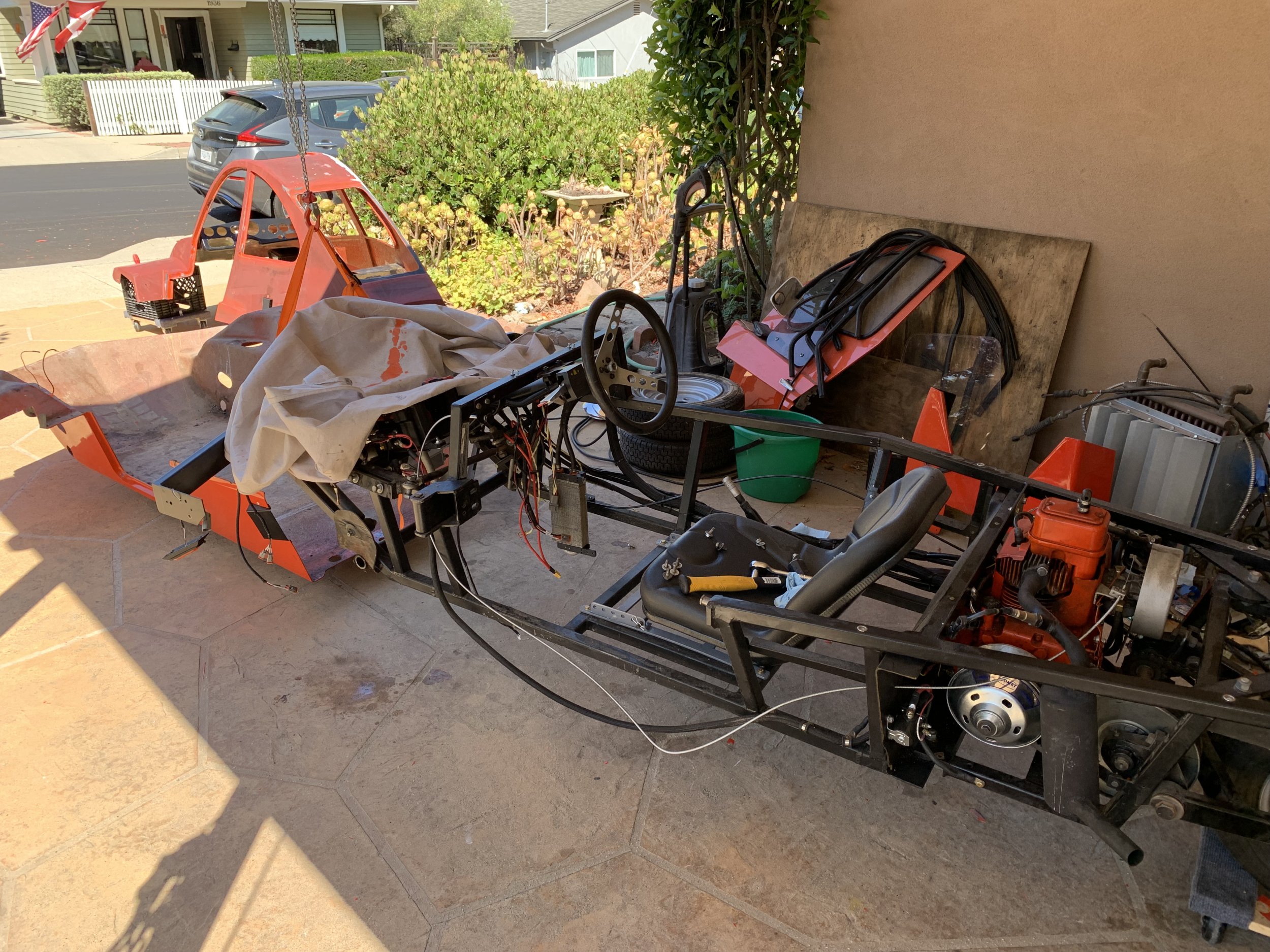
This is where another silly plan came into action. I’d seen an image somewhere of someone towing a freeway backwards, by putting a trailer hitch on the rear and lashing the rear suspension up, so that the drive wheel was off the ground. You then just need to fix the steering, and you have something that can potentially tow. So I did that.
More friends with pickups to the rescue, and we had successfully drug it back to my house.

I even had magnetic trailer lights for full street-legality.

I could then do a post-mortem. I initially assumed this was just a siezed piston/bearing, since I had removed the governor on the engine a while ago. My guess was it was a oil aeration issue since this is a splash-lubricated engine. However, checking the oil it looked fine, though this was admittedly a few days after the failure.

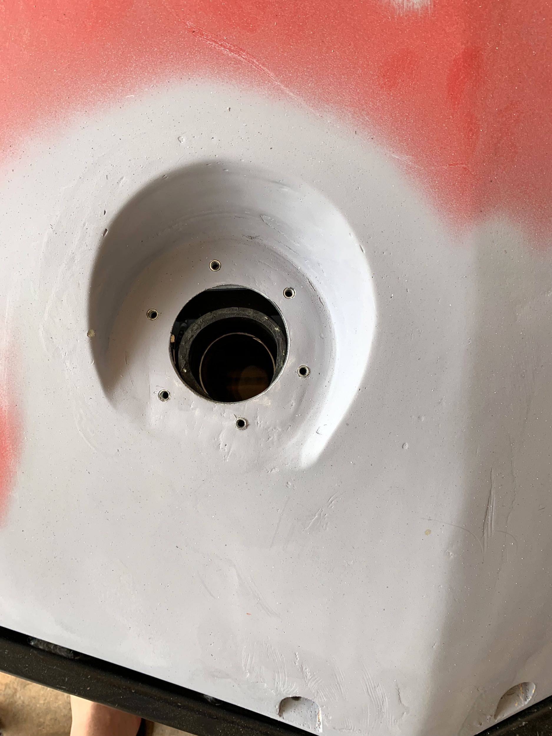
With the engine pulled, it was immediately apparent something was not right. That shaft should be centered in the seal, and I could wiggle it slightly. Interestingly, the flywheel was still stuck, though it also would move a few degrees.

With the side off, it was apparent what had gone wrong. The crankshaft had broken in half!

Pulling the bearings, it doesn’t appear the piston rod bearings were the source of the failure. Apparently this engine doesn’t have separate bearings, it just uses the connecting rod metal as the bearing surface. There are some wear marks, but it was smooth to the touch, with no grooving or any other damage other then the discoloration. The side of the bearing was rather dinged, since apparently the half of the crankshaft that included the connecting rod had rotated a few times before getting stuck, and in the process scraped the side of the rod up.

You can see the crack happened to one side of the bearing section, and the bearing section was in fine shape otherwise.

The end of the crankshaft still in the engine, connected to the flywheel was still partially siezed, only moving a bit. Looking at the pictures I took, there is aluminum scrubbed off on the broken section of the crank, so the piston rod + crankshaft half must have continued to rotate at least one time after the siezure.
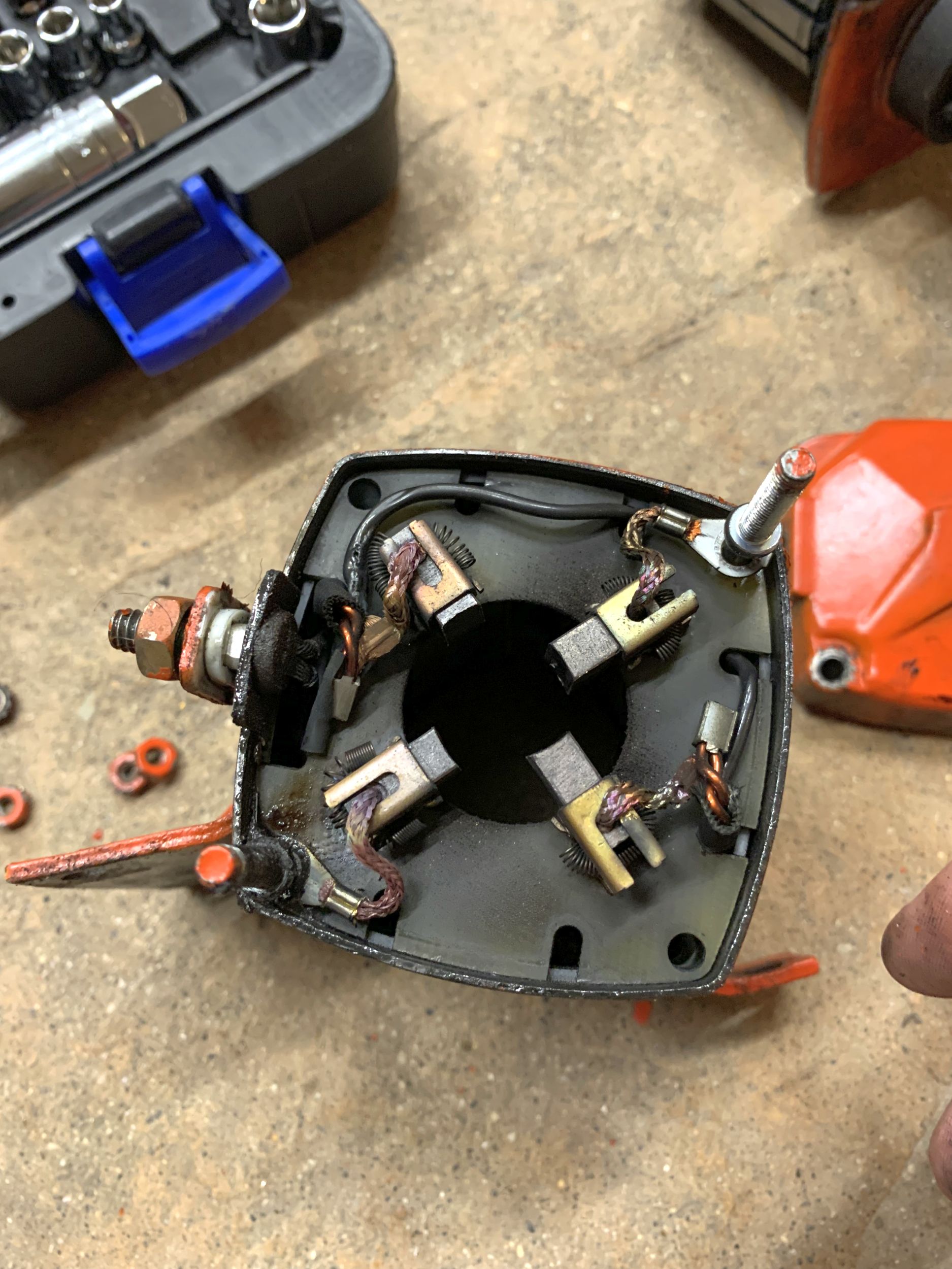
I then moved on to pull the flywheel/generator, and found what I believe to be the source of the issue.

With the flywheel off, there had pretty obviously been catastrophic failure. A bunch of the magnets were partially shattered, and wedging against the generator armature.


I don’t have a clear idea what triggered the failure, but the stator tooth that seems to have been the one that took the most damage is also the one that seems to have some obvious heat damage (see the dark colouring). It seems like that one tooth in particular had been getting extremely hot, enough that it discoloured the stator enamel.
My current hypothesis is that the entire failure was triggered by the stator contacting one of the magnets:
- One tooth of the stator contacts the magnets
- The contact causes a large chunk of magnet to fracture and break loose
- That magnet chunk wedges between the stator and the flywheel, causing it to abruptly seize
- The engine was running at > 3000 RPM at this point, so the momentum of the drivetrain was suddenly being transferred entirely through the crankshaft
- The torque on the crankshaft caused it to break in half.
This is entirely presuming that the failure started in the generator. It’s also possible the crankshaft broke, and that caused the generator to contact, but if true I don’t have an explanation for the extremely discolored tooth in the stator in that case.
Anyways, I have plans ™ to resolve the situation: