Monday, June 16, 2025

Freeway Gauges!

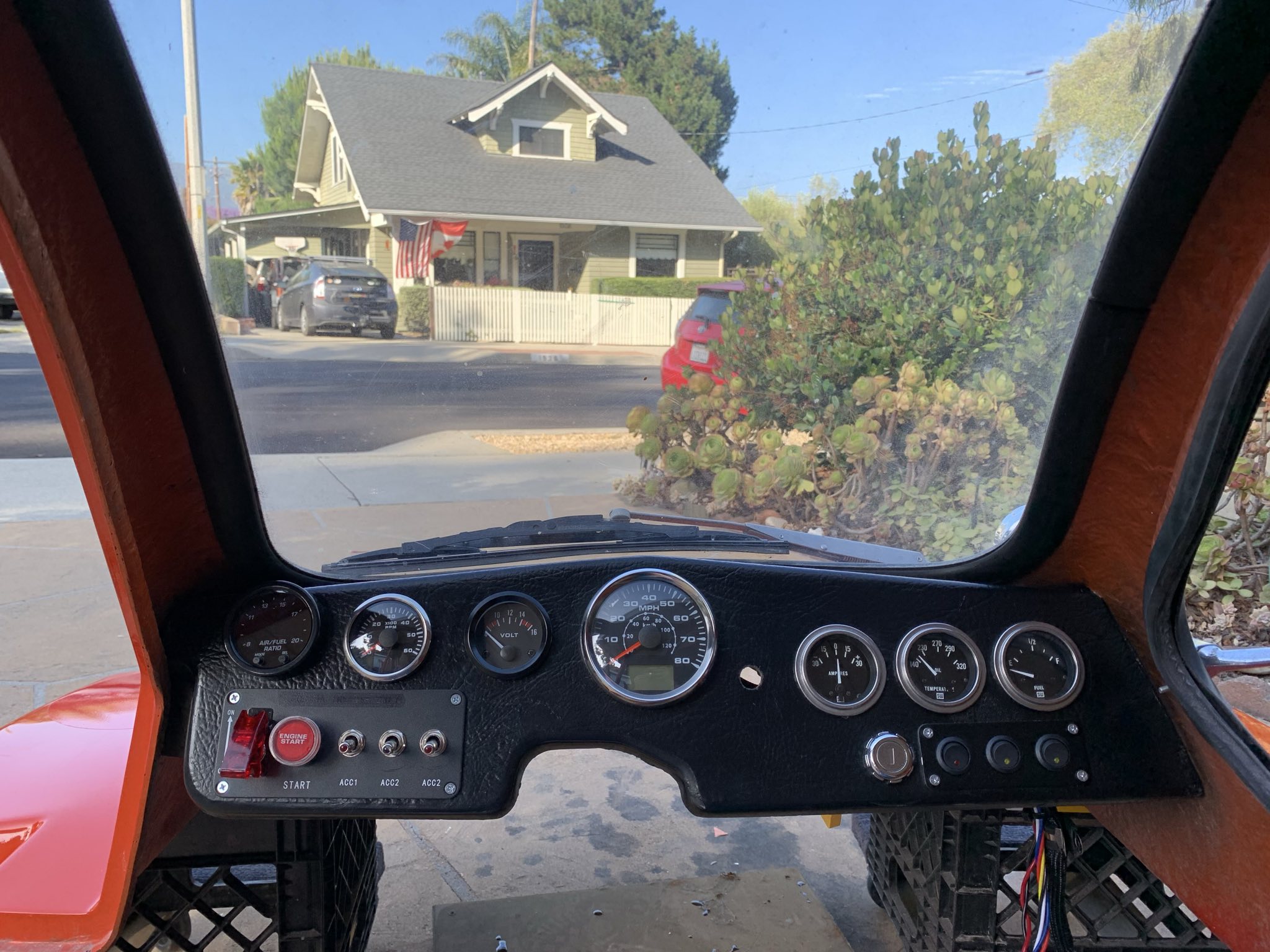
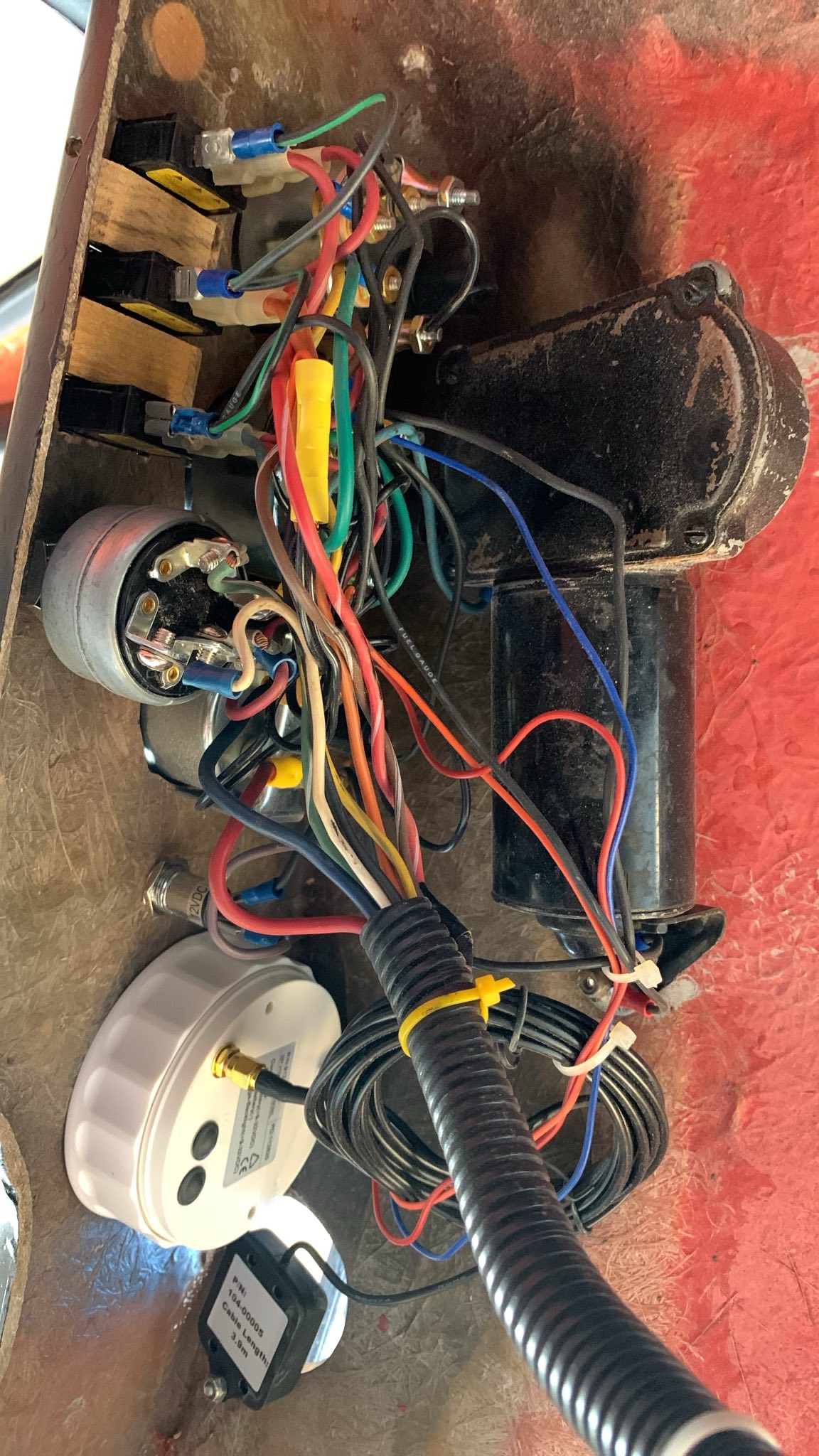
So, one area where I let things get a bit out of hand was the gauge situation on the freeway.

These originally came with 4 gauges: Speed, oil temp, fuel level, and battery current (plus and minus).

The Speedo is GPS-based. The original speedometer got water-damaged somehow, so the previous owner (tried) to replace it with a GPS unit. Somehow, when I took possession of the vehicle, it only worked when the engine was not running. I’m not sure how that was managed, I didn’t bother tracing any of the wiring since I have an original wiring diagram, and was planning on replacing all the wiring anywas.

Since I’m a nerd, I added a tachometer, a voltmeter and one more.

signal-2025-06-14-180052.jpeg

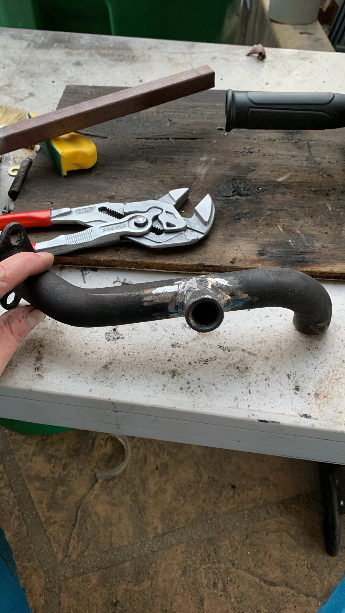
So one of my housemates is a jerk, and made a sarcastic comment about a O2 sensor. Well….

signal-2025-06-14-195722.jpeg

(Trust me, these welds looked really terrible before I ground them nice.)

IMG_8287.jpg

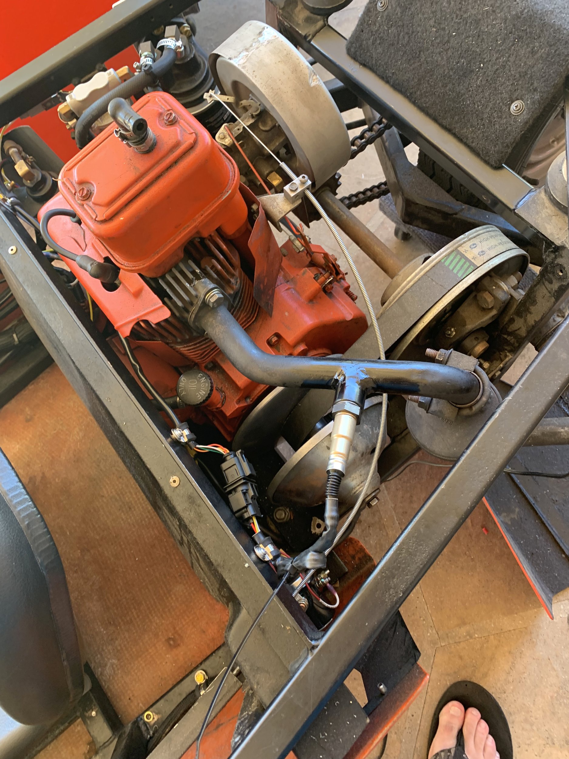
Terriblwelder strikes again, and I now have a O2 bung in the exhaust, and a Chinese clone of an AEM 30-0300 Wideband AFR gauge installed in it.

I had to shop around a fair bit for a bung that would work here, since most O2 sensor bungs have the sensor protrude maybe 1/4” into the exhaust pipe. Since the exhaust pipe here is about 1” ID, that would substantially occlude the pipe.

I managed to find a bung where the O2 sensor tip just barely peeks into the pipe ID when it’s fully screwed in. This isn’t a high performance application, I can handle the sensor response being maybe a tiny bit sluggish.

I can also confirm that the carb tuning is terrible. It idles around 10:1 AFR currently, which makes sense (it smells rich just running). I’ve not had it under load running yet.

——–

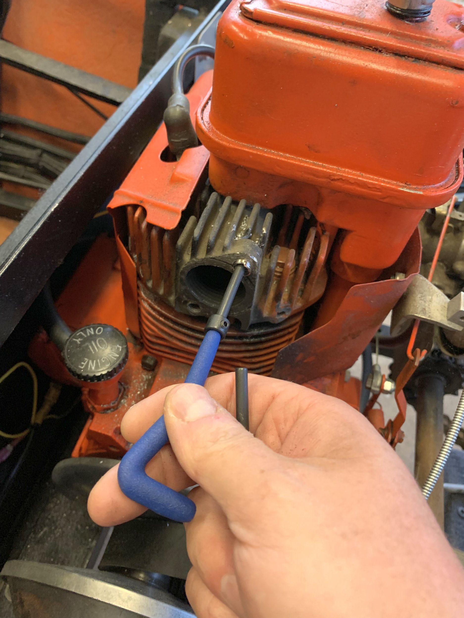
I also took the opportunity to helicoil one of the exhaust flange bolt holes, as it was on the edge of the threads being completely gone (the bolt in it did screw in, but it could rotate continuously with just a bit of resistance).

IMG_8285.jpg

Wiring the Freeway.

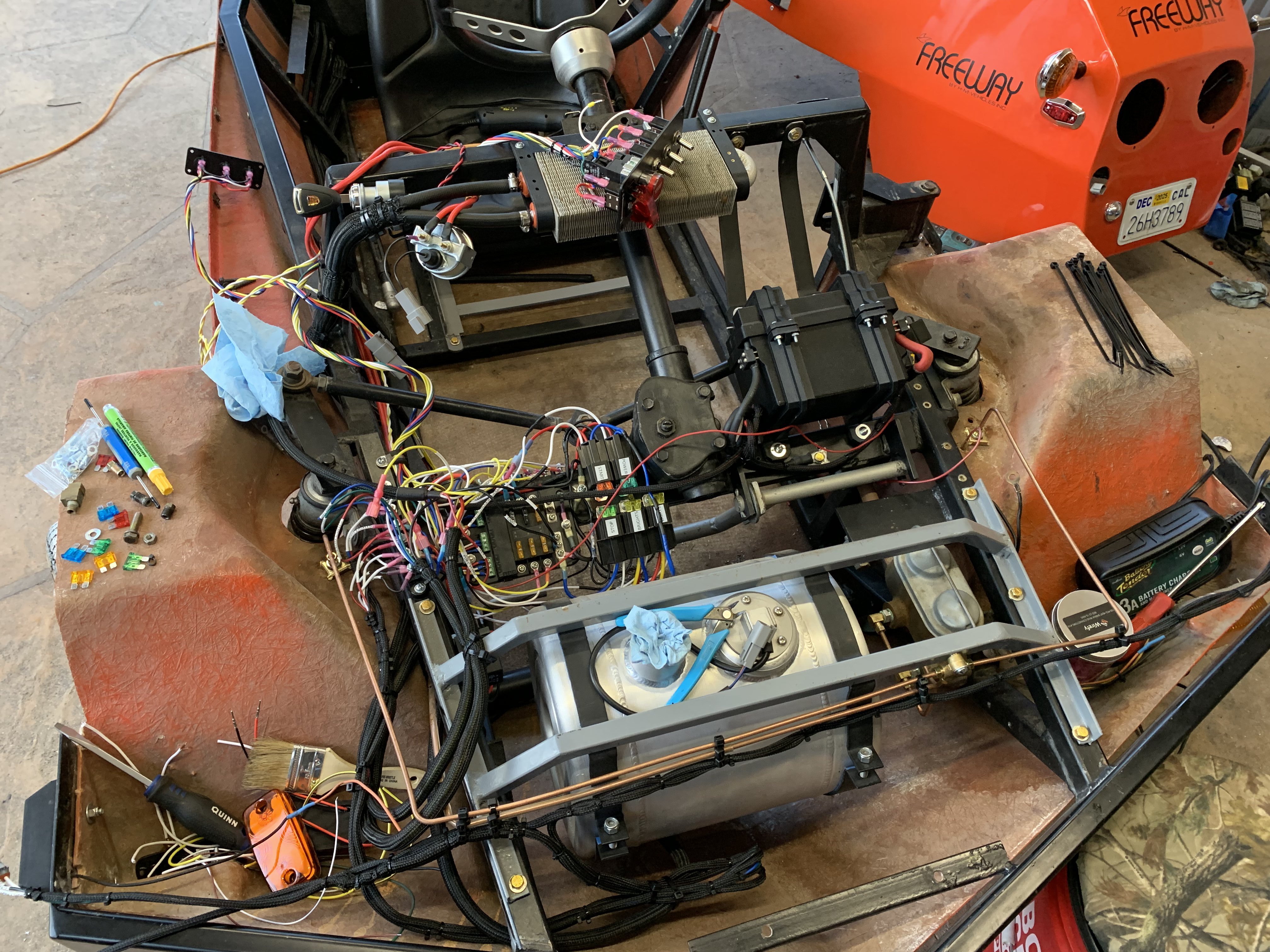
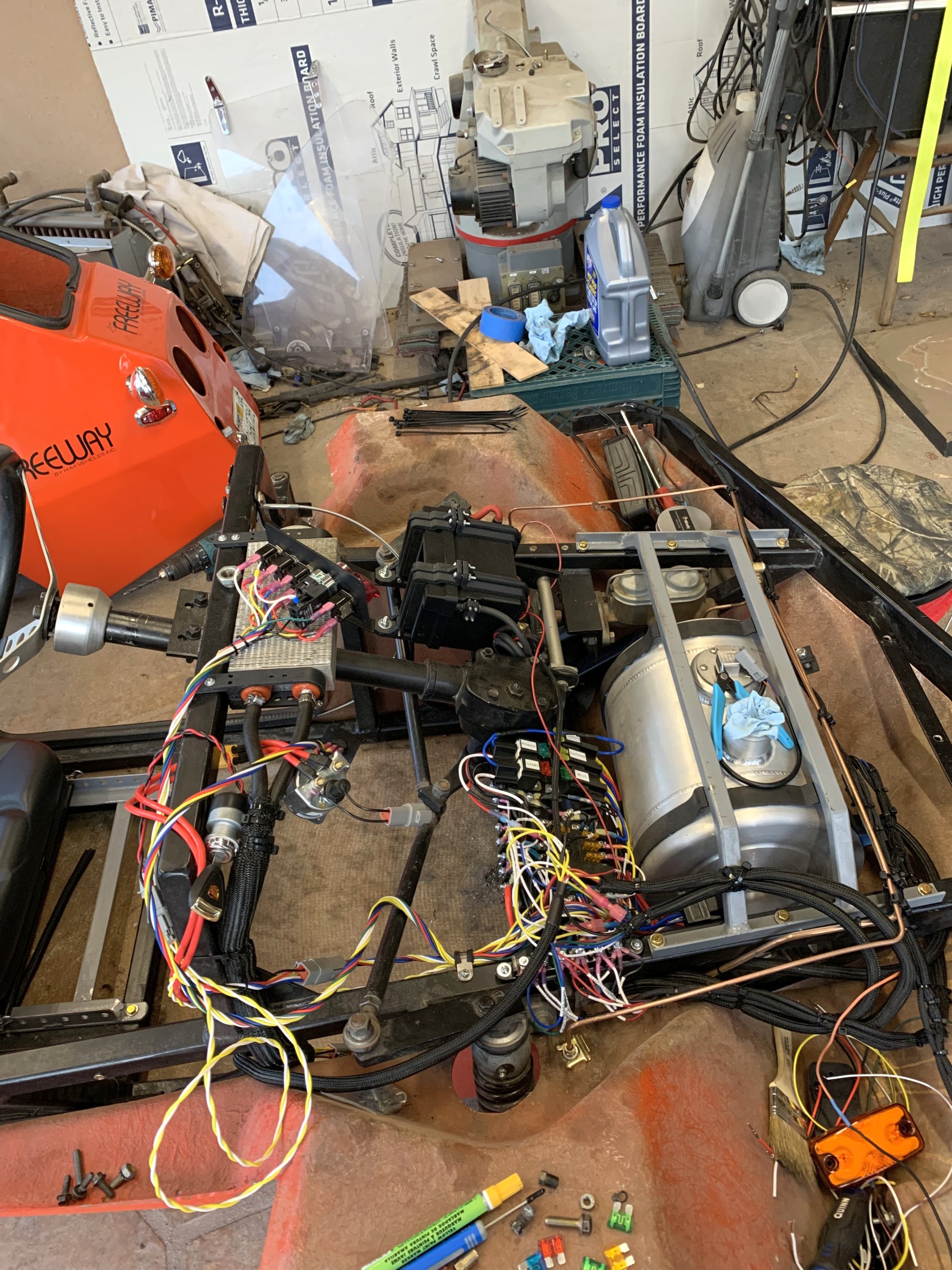
Like most of my projects, the wiring for the HMV Freeway got a bit out of hand.

IMG_8227.jpg

Electrics are an area where I’m quite comfortable, as some of what I do at work is effectively electrical engineering. In this case, I’m playing around using only relays, but well, I kept adding things I wanted, or needed a DPST relay to invert something, or so on.

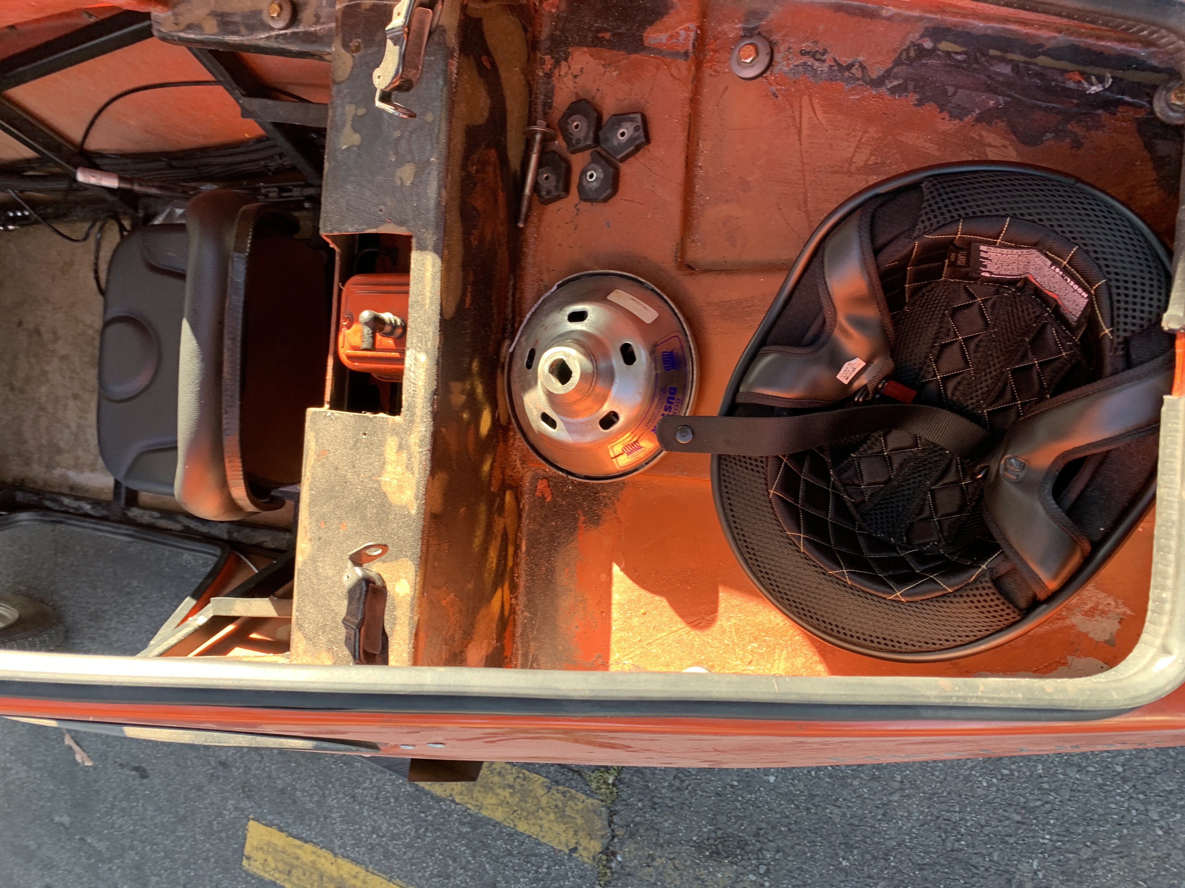
Everything is pretty carefully fused. I also relocated the battery up to the front area. The black box in the above image contains a lithium motorsport battery.

I have no idea how they do it, but the thing is ridiculously tiny, and weighs basically nothing. I’m guessing they’re basically those jump-starter packs in a battery case, with a integrated battery manager that somehow handles the charging and handles the lead-acid float-charge behaviour.

In any event, it seems to have plenty of gumption, and the engine turns over fine. There’s a 100A circuit breaker mounted to the side of the box, and apparently the starter doesn’t need more then 100A (or the thermal time constant is long enough that the current pulses when the engine does the compression stroke are short enough that the breaker doesn’t trip out).

You can also see I replaced the front brake lines with ones that would clear the fuel-tank structure.

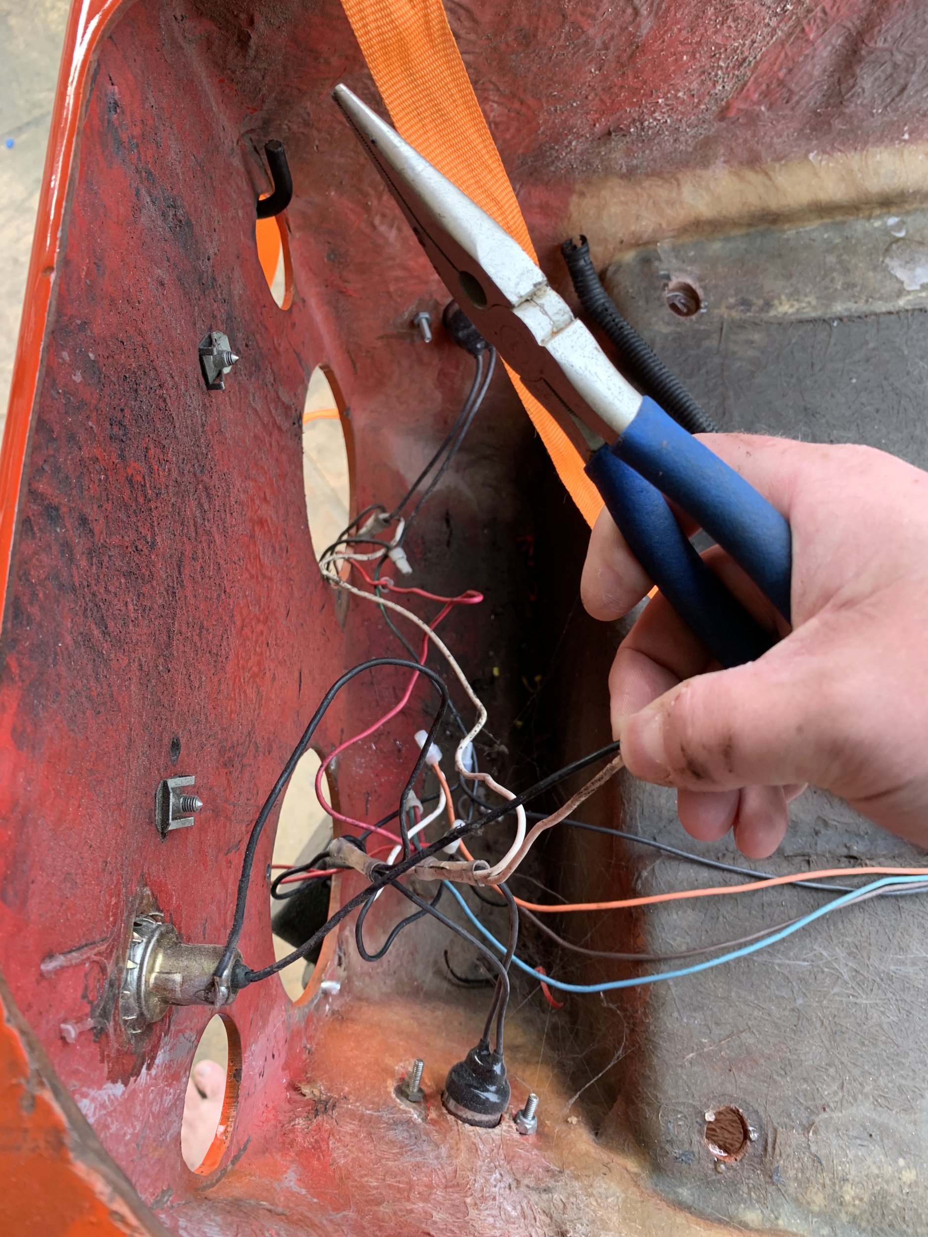
The original wiring on the freeway was…. not great:

IMG_8159.jpg
signal-2025-04-06-170713.jpeg

At this point, outside of the engine, I think there’s maybe 6” of wire that was originally on the thing remaining. And that 6” is just because the run/charge connector on the engine has a weird connector that I couldn’t find, so I just pig-tailed it.

I’ve gone through and everything is now connectorized. I’m using (chinese knockoff) Deutch connectors everywhere, and they’re working wonderfully.

IMG_8229.jpg

Additionally, everywhere the wires run along the chassis or could vibrate, I’ve wrapped them in protective sleeving. I also did the same for the oil cooler lines, and the fuel line that runs from the front fuel tank to the engine.

At this point, there’s 13 separate relays I’ve installed (14 if you include the blinker relay).

Freeway bodywork part trois

So, after the “exciting” adventure that was my attempts at painting, I had the brilliant idea “why don’t I just vinyl wrap the nose section”.

Well, it turns out that while most modern cars are generally fairly shallow curves and flat sections, the HMV Freeway is….. not. I spent probably an hour trying to figure out how to conform a sheet of vinyl to the front without luck. With the protruding nose, and how it blends into the side rail features, you can’t really conform a sheet of material to it.

Anyways, I wound up wasting most of a $60 roll of vinyl, only to throw most of it away. Thinking about it now, I think I can see a way to do the nose section by using multiple vinyl sections, but again, I’m running low on willingness to futz with bodywork at this point.

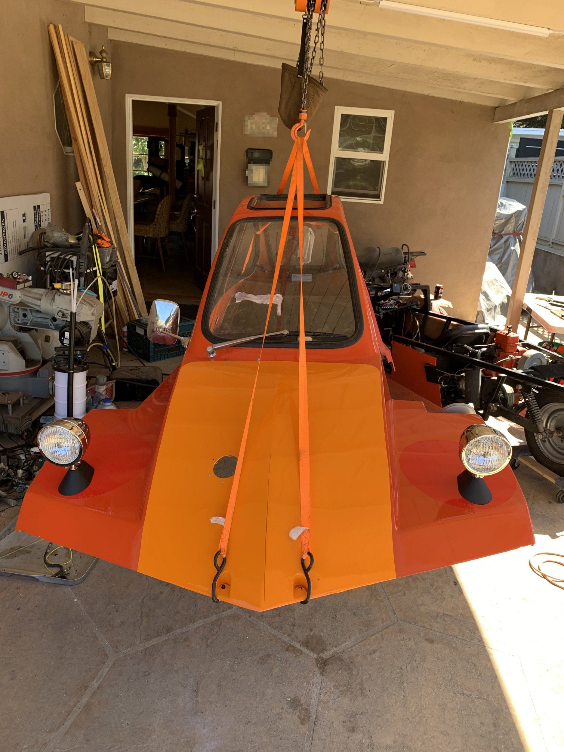
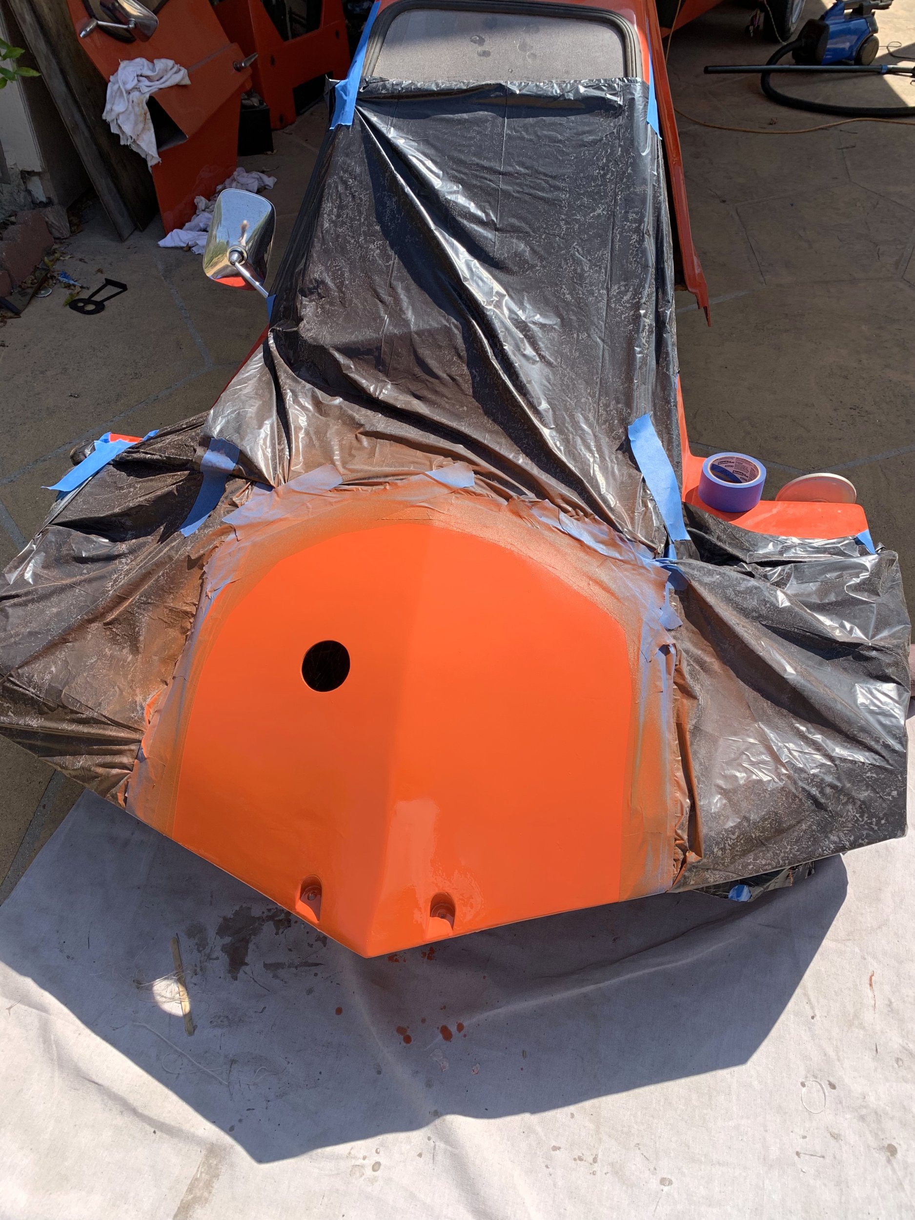
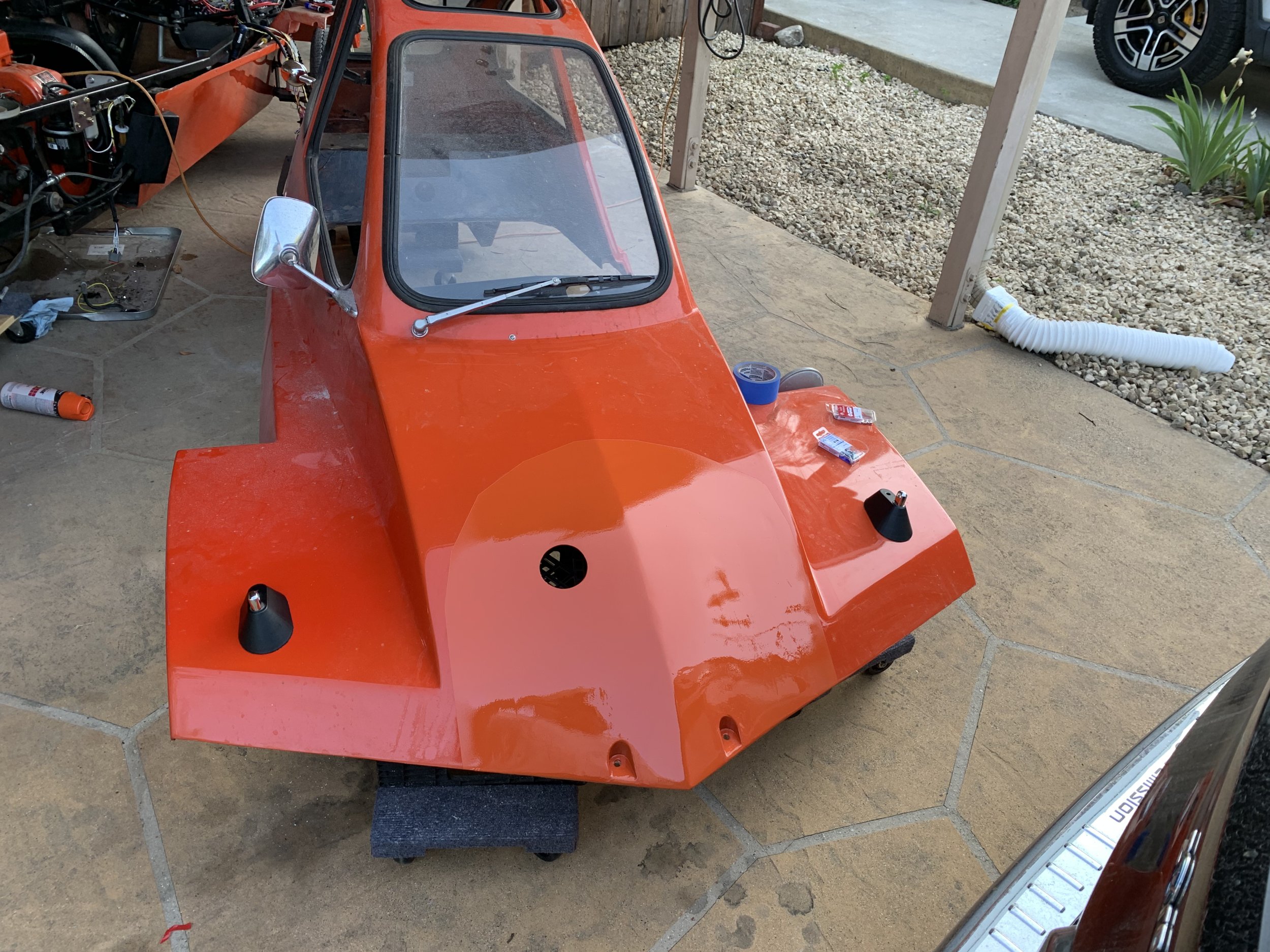
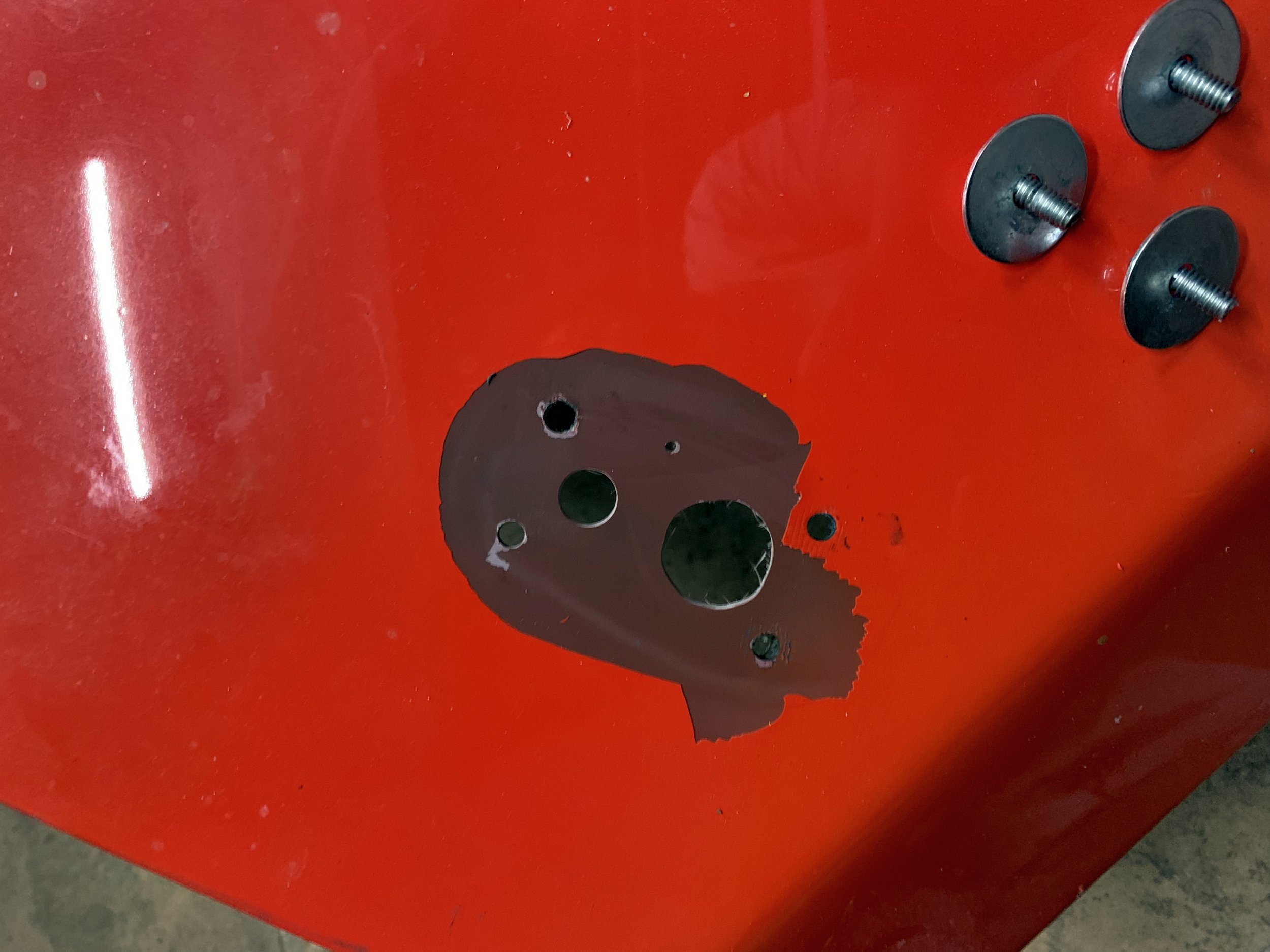
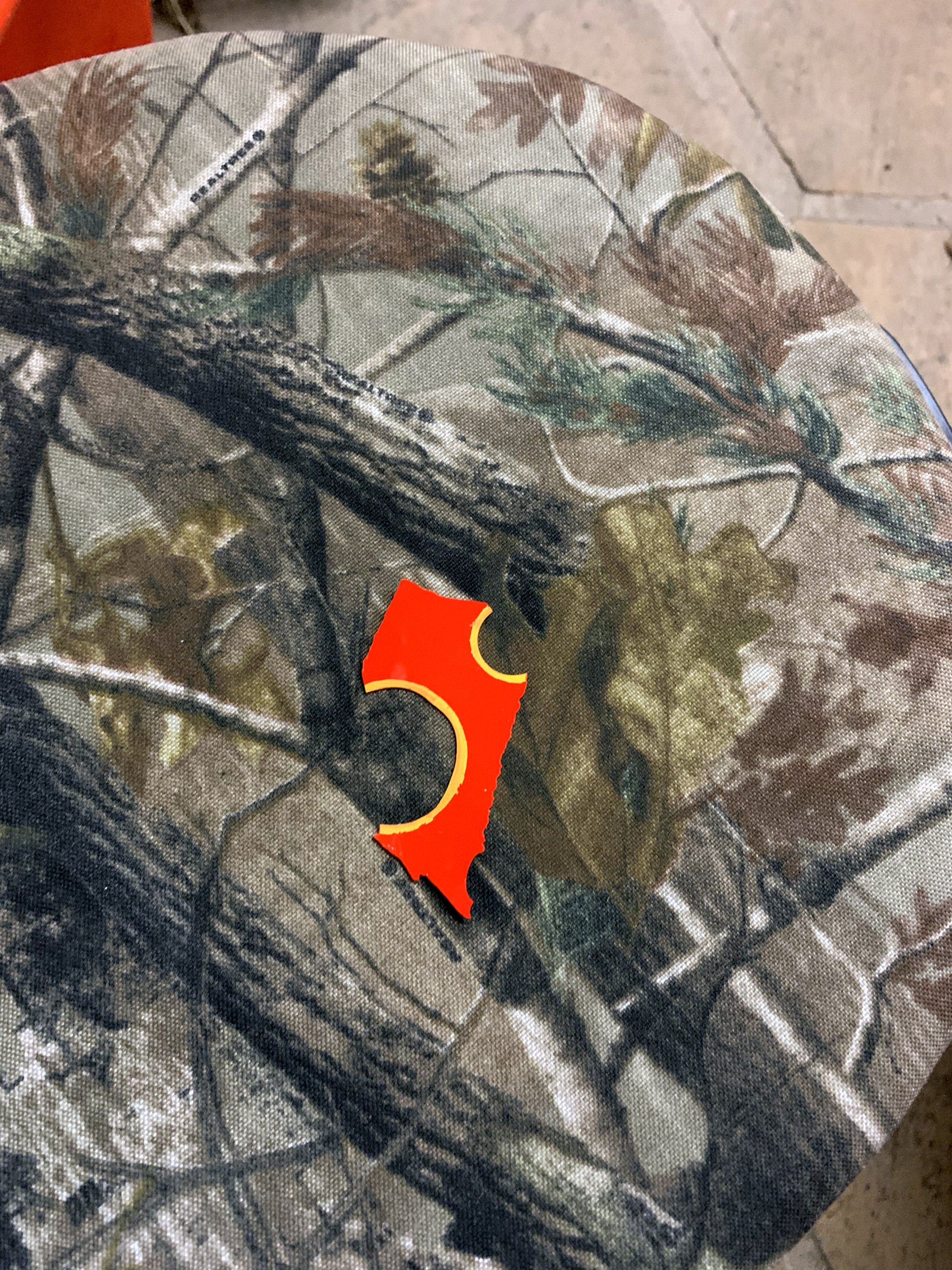
Currently, I have the nose section coated with vinyl wrap, and some circular dot stickers over the places where paint got ripped off when I removed the previous headlight mounts.

IMG_8288.jpg

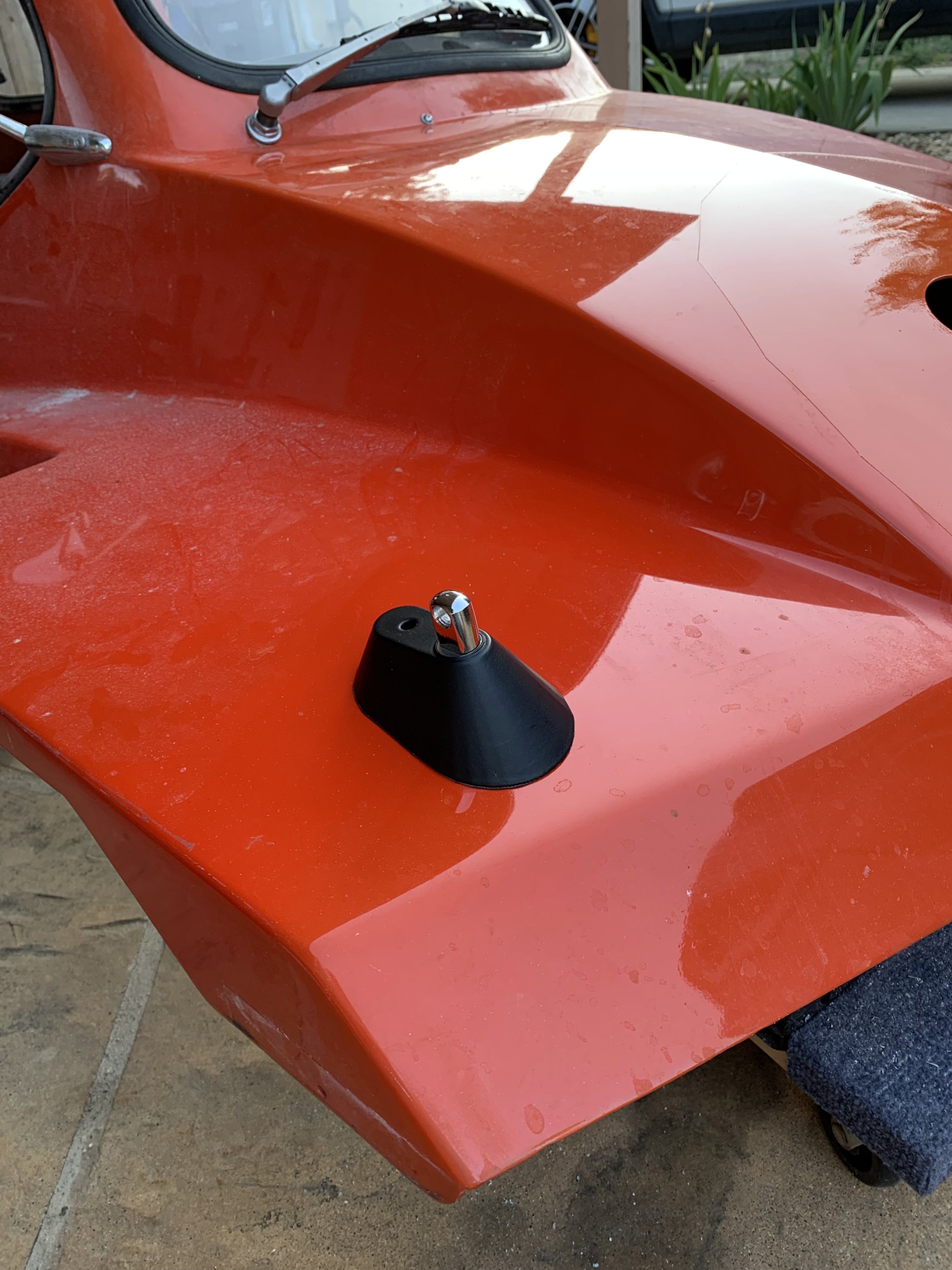
I’ve also moved on from using adhesive tape in addition to the screws to mount the headlights, they currently just have a gasket made of neoprene foam rubber stuck to the underside to help seal them against the body (not that that matters, there’s a lot of other areas which would leak in the rain anyways).

Like most projects where you do something for the first time, I now can think of a bunch of ideas that would (maybe) resolve a bunch of the problems I had.

Ugh.

Freeway bodywork part deux

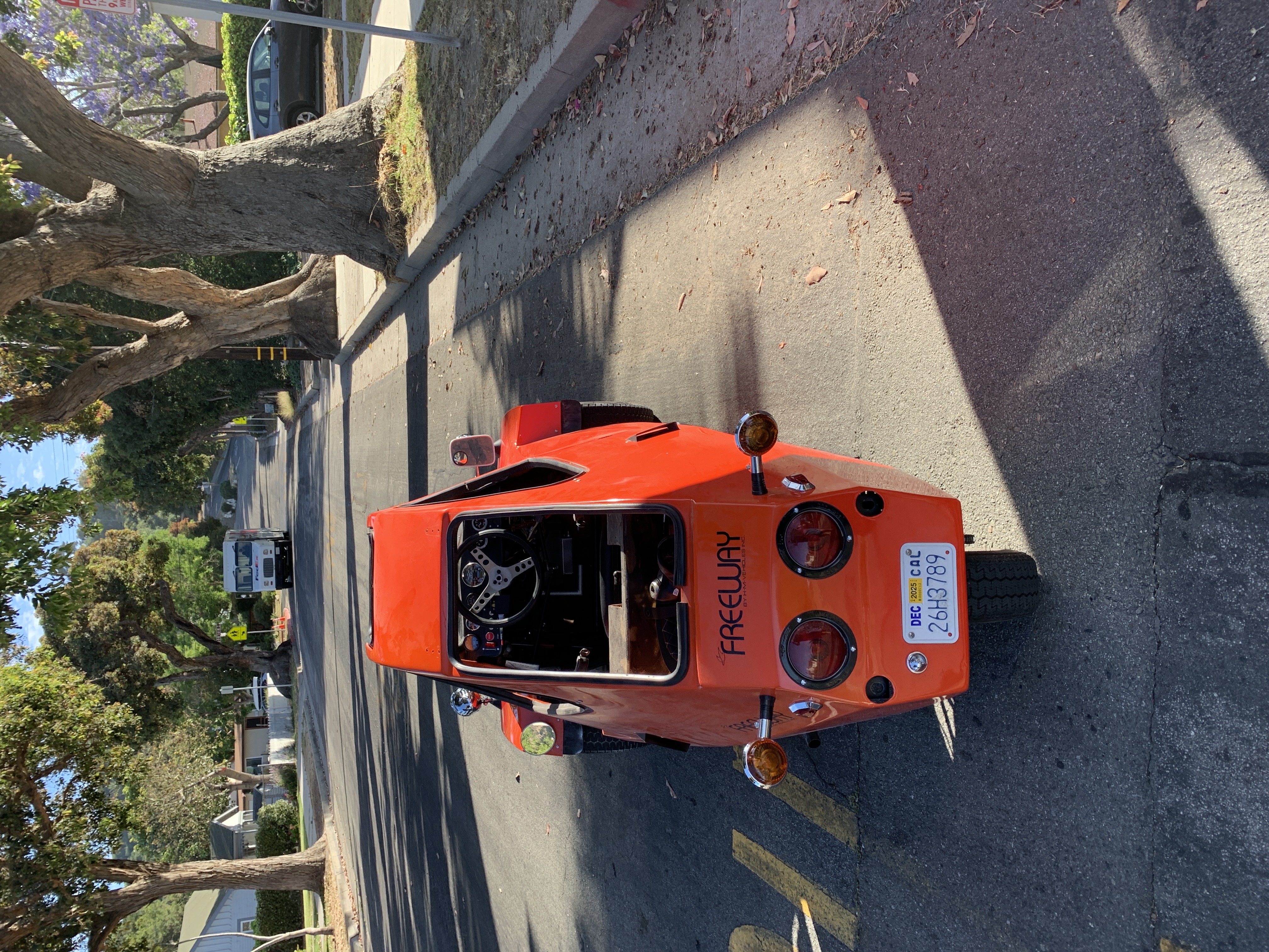
So I’ve been working on the HMV Freeway a bunch recently. I actually have it driving (until the CVT drive pulley, which I forgot to tighten properly left the building with a bang), but I’m backing up a bunch here to try to go over what I’ve done.

So, after the last post, I had fiberglassed-in the nose, but the exterior face was still very concave, because I didn’t have the mold working right. I ran with it, but it needed a lot of finessing.

signal-2025-05-16-174128.jpeg

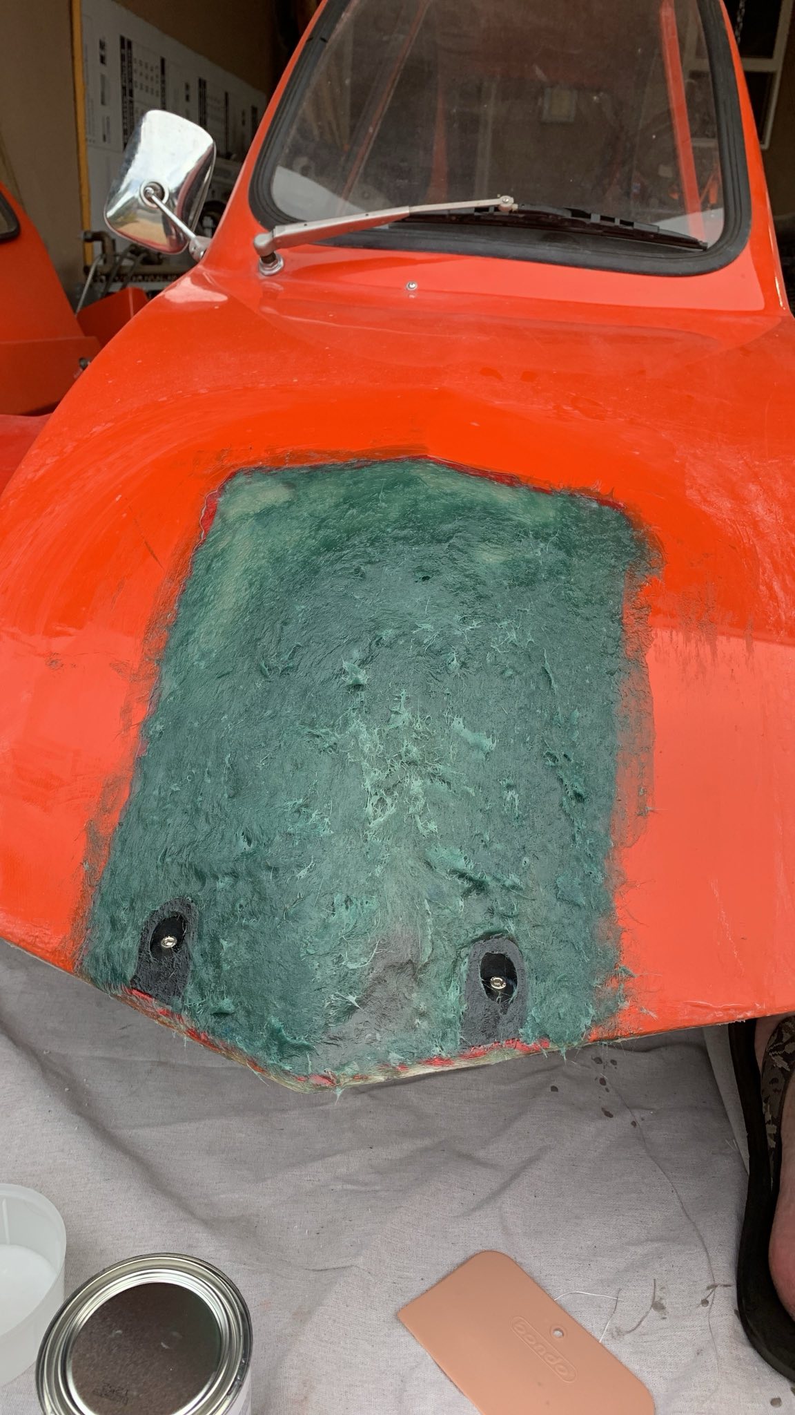
First step was do the major filling. This is 2 lbs of bondo hair (yes, really). Basically, it’s bondo mixed with chopped fiberglass. You can also see there are two little 3d-printed mold insets to shape the screw cavities in the mess. They were treated with parting wax, and came out very easily afterwards.

This worked well, except I had once spot that didn’t cure well. I suspect this was mostly because the fiberglass in this makes it very difficult to completely mix, and I was mixing way too much at once (basically, all of it), so I didn’t have time to be super thorough before it started cooking off.

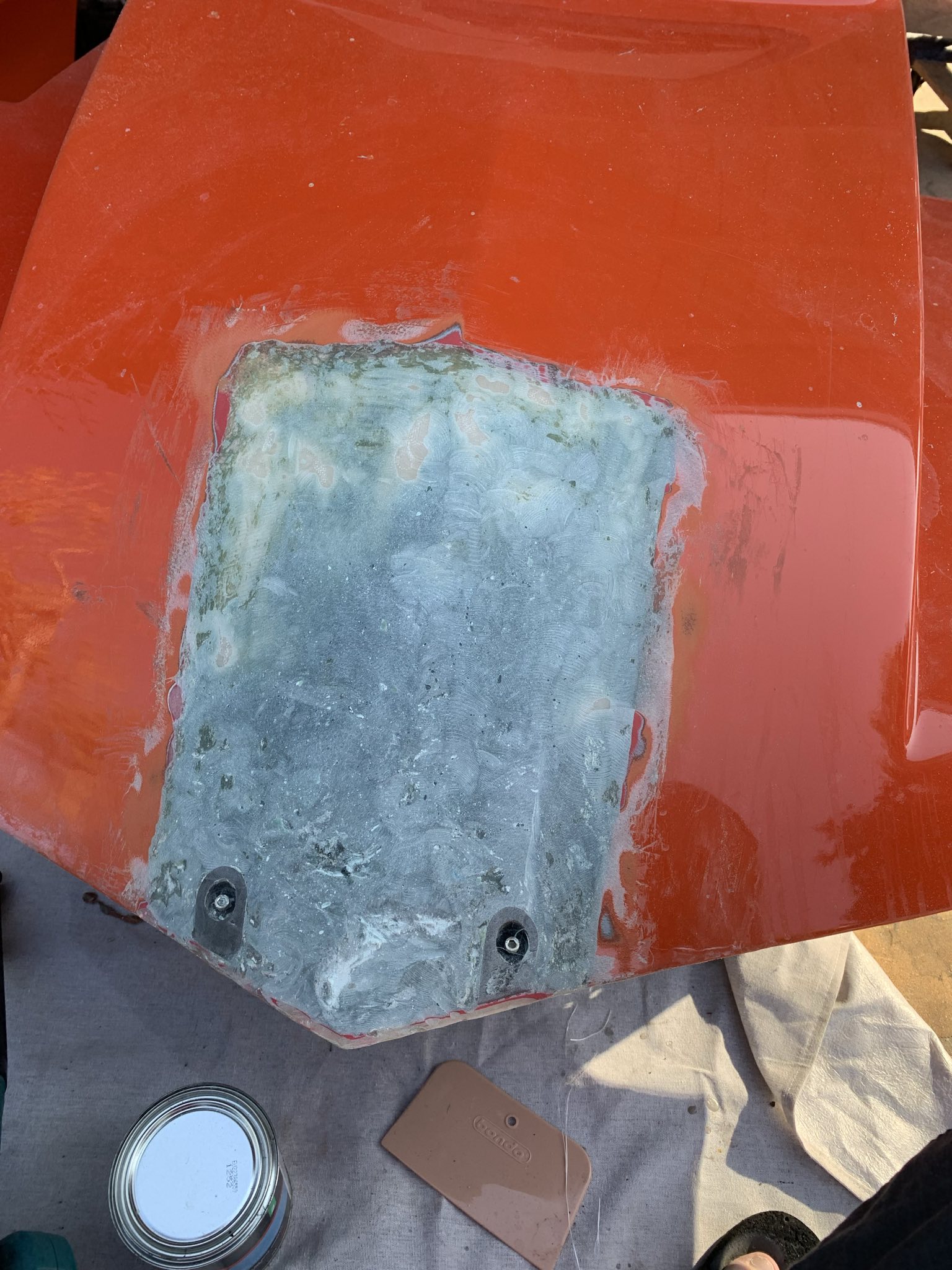
I then sanded it smooth(ish).

signal-2025-05-17-174026.jpeg

I then had the brilliant idea “why don’t I just cover all this crap with vinyl wrap.”

It turns out doing vinyl wraps well is freaking hard, and I think the whole nose of this might be one of the most difficult shapes to wrap properly. Most cars are mostly flat surfaces, or simple one-axis arcs. This….. is not.

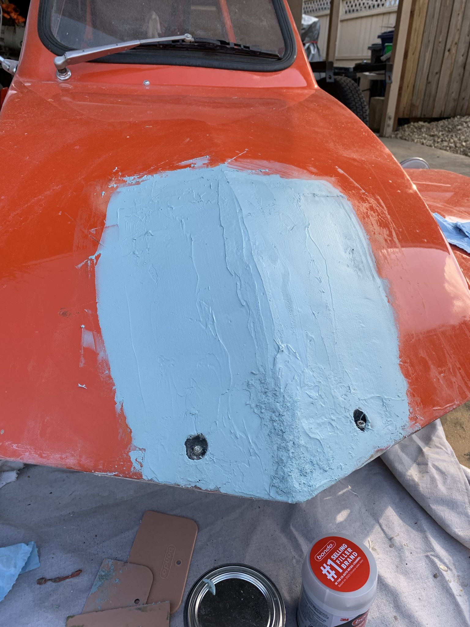
And then moved onto normal bondo.

signal-2025-05-17-174036.jpeg

I then spent the next 2 or so weeks trying to get a good paint result that I liked. This is made harder by the fact that this has been repainted at some point (it originally Red!). At this point, I think I’ve tried every version of spray-paint orange I can find locally.

IMG_8258.jpg

I’ve also done a few more sanding/bondo cycles. The crease carrying over the nose is still not quite where I want it to be, but I’m giving up at the moment.

IMG_8260.jpg

I had ideas about the thing being two-tone, but that would involve shaping the color on the front a lot more carefully. I may revisit this idea.

I’ve also had a bunch of other stupid issues that make the paint even more complicated. I 3d printed some light mounts, and then installed them:

IMG_8259.jpg

Of course, because I’m an idiot, I put the left-side one on the right, and vice versa. I also used some foam rubber double-sided tape to seal them on, and when I went to pull them off, well:

IMG_8264.jpg
IMG_8265.jpg

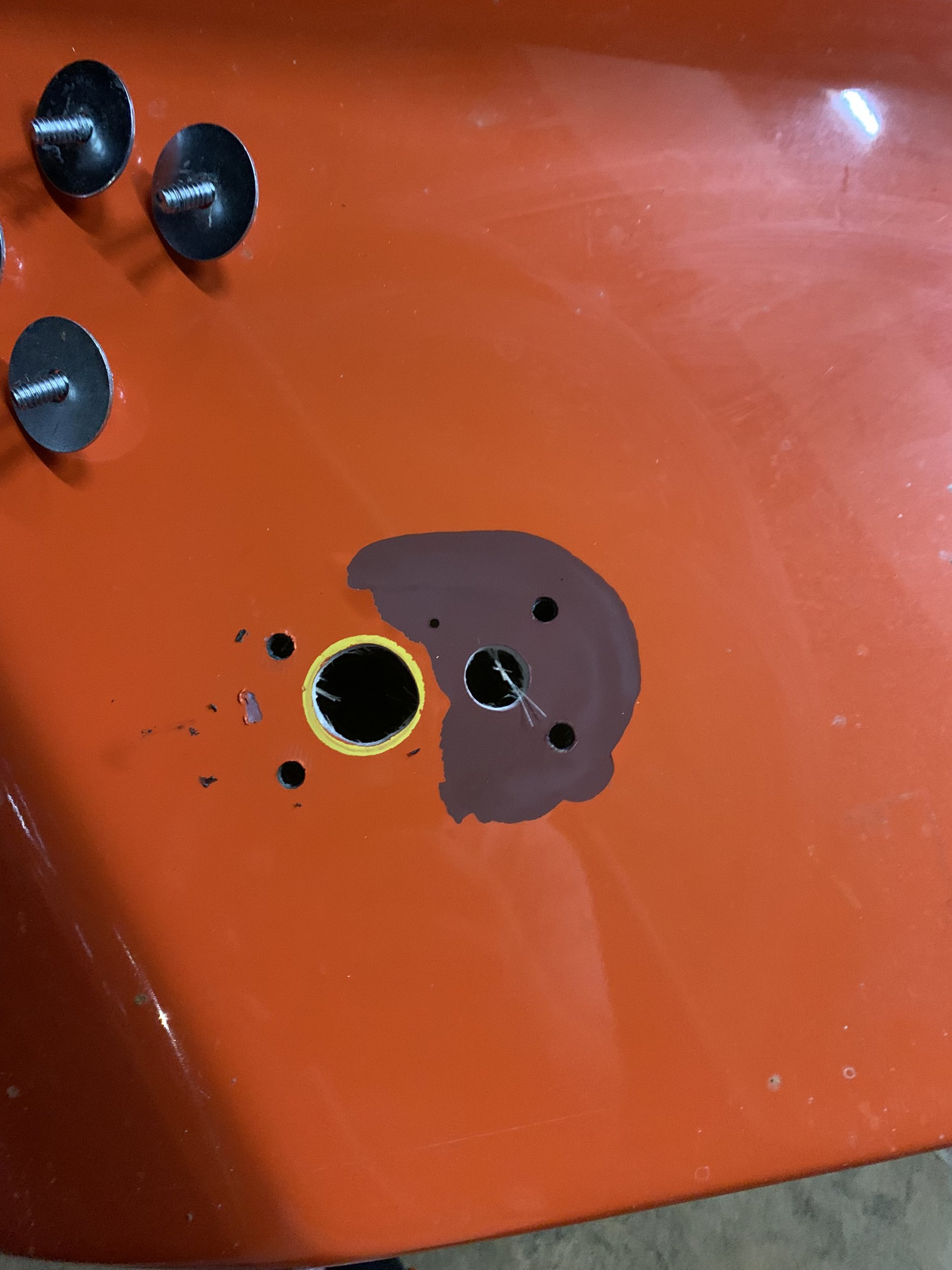
The paint just peeled off in sheets. There were large sections where there was no double-sided tape involved, it just flaked free:

IMG_8266.jpg

Yep, whoever did the paint the previous time did a shit job, and the color coat delaminated from the primer. I’m confident that there is primer becase when I sanded through it on the nose area, it comes up bright red. The dark burgundy is between the orange paint and the red.

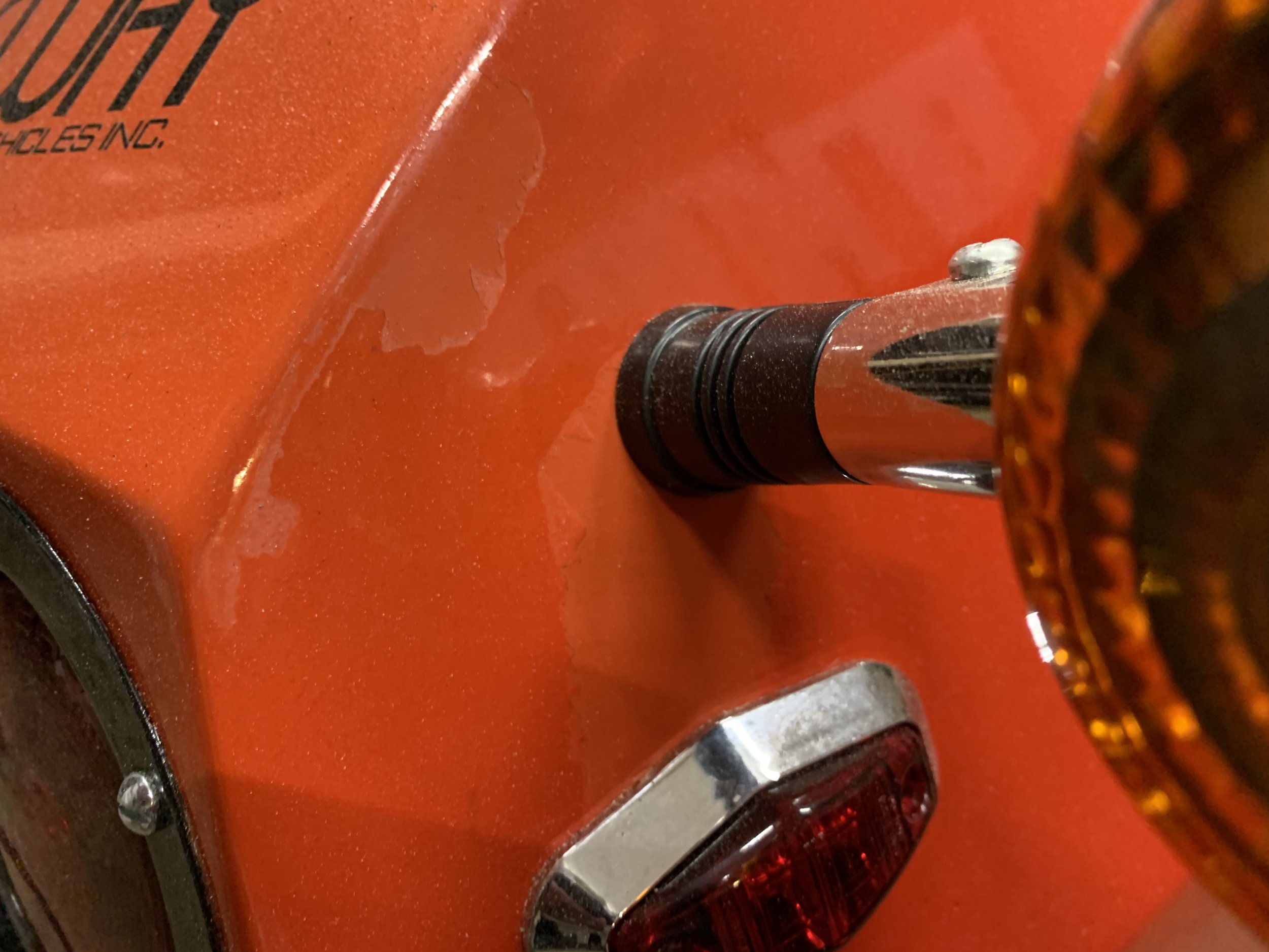
This isn’t the only area where the current paint-job is…. not great. On the rear section:

IMG_8263.jpg

I installed some additional turn-signal indicators from a motorcycle, because the two tail lights on this thing are effectively indistinguishable from a distance. When doing this, I put some blue painters tape on the body, marked that with a sharpie, drilled, and when I went to remove the blue painters tape (after maybe 40 minutes), it pulled big chunks of the clear-coat off.
Sunday, May 18, 2025

Freeway Bodywork!

So, since I am relocating the fuel tank to the front of the freeway to accommodate the moved seat, that means I need to cut out and fill in the existing headlight bucket, since it protrudes a long way into the interior where the fuel tank is now located.

signal-2025-04-26-192511.jpeg

I spent a bunch of time trying to get a good measurement of the front-end geometry, to make a mold for the replacement fiberglass. I initially was hoping to use the 3d scanner I have (a revopoint metro-x), but it doesn’t have the greatest tracking, and the gloss paint finish really makes scanning the thing extremely difficult.

I sprayed it down with scanning spray, but that was after I had applied all the tracking markers, and the scanning spray is apparently matte enough to block the tracking marker dots.

Anyways, I eventually wound up using the non tracking dot based scan mode, and got something usable. I then 3D printed a mold block to try to glass-against.

Moving on, I flipper the body top over and got to hacking:

signal-2025-05-02-171222.jpeg
signal-2025-05-02-172138.jpeg

I then feathered the edges of the cutout down to a sharp edge by sanding them down on the interior of the shell, and trying to be clever, attempted to use a vacuum pump to conform a silicone sheet to the geometry of the 3d printed mold, and also to hold the mold in place:

signal-2025-05-03-143428.jpeg

While the vacuum held the mold on fine, it didn’t have enough grunt (or there was a leak I didn’t find) to pull the thin silicone sheet into the full mold geometry. Since I wanted to get this done, I just went with it. I’m going to have to add a /bunch/ of filler to properly shape the nose out in the future, but the strength is back in it, in any event.

signal-2025-05-03-143419.jpeg
signal-2025-05-03-143405.jpeg

I wound up doing 2 layers of fiberglass, and then going to get food, before removing the mold and then adding more layers.

Of course, a bird took the opportunity to poop on the new fiberglass while I was at lunch.

signal-2025-05-03-154552.jpeg

I eventually wound up with 8 layers of fabric feathered into the existing body.

signal-2025-05-03-164115.jpeg